

Monolithic difference amplifiers are integrated circuits that incorporate an operational amplifier (op amp) and four or more precision resistors in the same package. They are incredibly useful building blocks for analog designers who need to convert a differential signal to a single-ended one while rejecting common-mode signals. For example, the INA134, shown in Figure 1, is intended for use as a line receiver for differential audio interfaces.
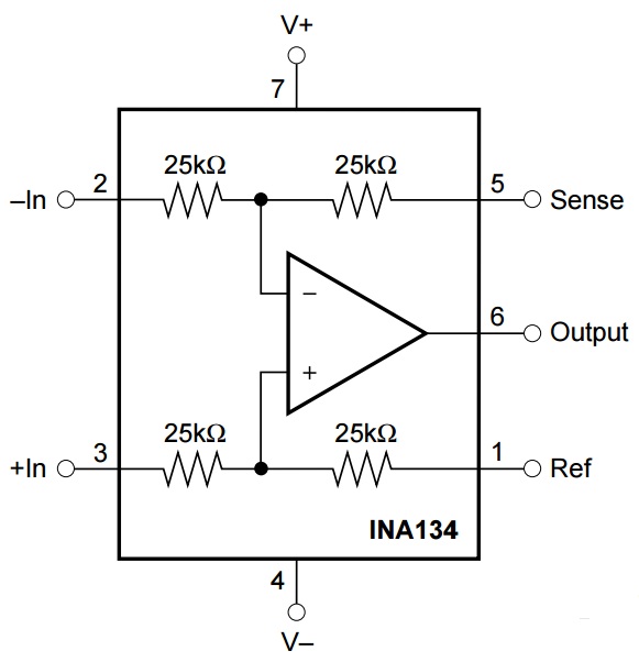
Figure 1: A simplified internal schematic of the INA134 differential line receiver
Although most designers are comfortable with this simple building block, I find that one aspect of their use is commonly overlooked: the two inputs of a difference amplifier have different effective input resistances. By “effective input resistance,” I mean the input resistance resulting from both the internal resistor values and the op amp’s operation.
Figure 2 shows a typical configuration of the INA134 with input voltages and currents labeled, as well as the voltages at the input nodes of the internal op amp.

Figure 2: Relevant voltages and currents for the effective input resistance analysis of a difference amplifier
For each input, Equation 1 defines the effective input resistance as:
![]()
Let’s start with the easy part first: the noninverting input. Looking at the diagram in Figure 2, you can see that R3 and R4 are in series. Assuming that no current enters or leaves the op amp input, Equation 2 calculates the effective input resistance as simply:
![]()
Now let’s focus on the inverting input. Recall from the ideal op amp rules that the two inputs of the op amp should always be at the same potential (Equation 3):
![]()
You can also see that R3 and R4 form a voltage divider at the noninverting input. Equation 4 calculates the voltage at the op amp’s noninverting input (VP) as:
![]()
Why is this important? Well, this voltage partly determines the effective input resistance of the inverting input. Consider that the current through R1 (IIN(N)) is the voltage across it divided by its resistance (Equation 5):
![]()
Substituting Equation 5 for input current back into Equation 1 gives you Equation 6, a generic equation for the resistance of the inverting input:

Since you know the voltage at the inverting input (VN) will be equal to the voltage at the noninverting input (VP), you can replace VN in Equation 6 with Equation 4 to get Equation 7:
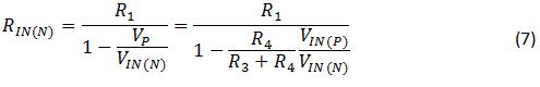
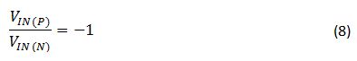
Notice that the effective input resistance at the inverting input actually depends on the ratio of the two input voltages. To understand how this might affect your application, consider an example: the INA134 used in an audio-line-receiver application where the voltages at the two inputs are equal in magnitude but opposite in polarity (Equation 8):
Referring back to Equation 2, the effective input resistance at the noninverting input is fairly straightforward:
![]()
However, the inverted relationship of the two input voltages has a drastic effect on the effective input resistance at the inverting input (Equation 9):
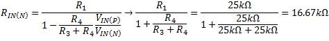
The effective input resistance at the inverting input is one-third that of the noninverting input. Thus, you must consider the lower impedance of the inverting input when choosing input coupling capacitors or filter circuits. Furthermore, any amplifier driving the difference amplifier inputs must be capable of driving the lower impedance at the inverting input.
With simple circuits, it’s often the most basic aspects of their operation that cause headaches in the lab. Don’t overlook the obvious!
Additional resources
- Check out our broad Audio portfolio
- Learn more about INA134 audio differential line receiver
- See TI’s Complete Portfolio of difference amplifiers
Top Comments
John, the incremental impedance DeltaV/DeltaI when looking into the positive input is R3+R4 the same as you state, but the corresponding incremental impedance is just R1 when looking into the diff amplifier…
Hi Ken,
Thanks for bringing this to our attention. To me, the INA133 datasheet is correct and the INA134 datasheet may need to be updated. We can calculate the common-mode input impedance pretty quickly…
-

tim hughes
-
Cancel
-
Up
+2
Down
-
-
Reply
-
More
-
Cancel
Comment-

tim hughes
-
Cancel
-
Up
+2
Down
-
-
Reply
-
More
-
Cancel
Children