

This technical article was updated on July 23, 2020.
Today, we continue our series on successive approximation register (SAR) analog-to-digital converters (ADCs) input types. Previously, I reviewed input considerations and pnoise performance comparisons between SAR ADCs. In this post, we will look at the source for Total Harmonic Distortion (THD) in a SAR ADC and how it differs between various input types.
THD Impact
Let’s first look at how harmonic distortion is introduced. A converter is essentially a non-linear system. If the system was perfectly linear, the input “x” would appear in a linear form at the output as “mx+b”. However, because of the non-linear behavior of the sampling and conversion capacitors, and quantization, when a signal “x” passes through a non-linear system, the ADC introduces DC and higher order error terms (x2, x3, etc.) at its output.
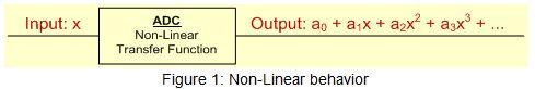
When you look at the output in frequency domain, each higher order term (x2, x3, etc.) results in spurs. These occur at integral multiples of signal frequency and are known as harmonics.
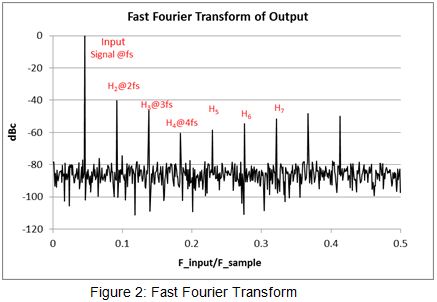
This can be intuitively understood using basic trigonometry. A Fourier expansion of the input signal consists of summation of sine and cosine terms (sin (2πƒt), cos (2πƒt)). When such a signal passes through a non-linear ADC, the output will be made up of DC component (a0) and other higher order error terms (x2, x3 → sin2 (2πƒt), cos2 (2πƒt), sin3 (2πƒt), cos3 (2πƒt), etc.) in addition to the fundamental. Let’s look at the trigonometric expansion for couple of higher order terms.

As seen from Table 1, each higher order term results in spurs at the output which appear at integral multiples of fundamental frequency 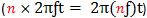 . Same is true for other higher order terms such as x4, x5 etc. It is the power of these components
  that introduce harmonic distortion.
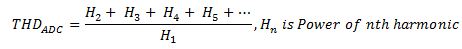
The THD of an ADC represents the relationship of power of the harmonic components (typically first nine) generated at the output to the fundamental signal power. It can be computed using:
Typically, Differential input SARs have better THD than single-ended SARs… Why is that so? Let’s now look at the mathematical expansion of the signal at the output of the non-linear ADC to understand this behavior.
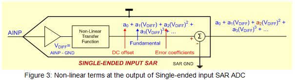
In single-ended SARs, due to non-linear behavior, DC offset (a0) and conversion error coefficients (a2, a3, etc.) from higher order terms (V2DIFF, V3DIFF, etc.) show up at the output. However, all error coefficients including even power terms (a2, a4, etc.) propagate beyond the summing node as shown in Figure 3.
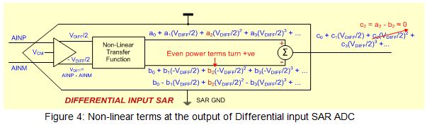
With differential SARs, the even power terms change sign to become positive. With good common mode rejection, pairs of even terms ([a2, b2], [a4, b4], etc.) get nullified at the summing node due to change in polarity. As shown in Figure 3, the even terms ([c2 = a2 – b2], etc.) are either absent or can be reduced substantially at the output, resulting in better THD.
For the best performance, knowing such differences in noise and AC performance can help one choose the SAR with the right input type. This is especially helpful when choosing the input configuration for the ADS886x family or for ADCs supporting multiple input types, such as the ADS8363, ADS7263 or ADS7223.
Get more tips from our SAR ADC blog series including:
-

Amit Kumbasi
-
Cancel
-
Up
0
Down
-
-
Reply
-
More
-
Cancel
Comment-

Amit Kumbasi
-
Cancel
-
Up
0
Down
-
-
Reply
-
More
-
Cancel
Children