

My last post introduced the concept of signal aliasing and how it manifests itself in data-acquisition systems. When out-of-band signals alias into the passband, they overlap lower frequency content and mask the true signals you’re trying to measure. To help filter any signals beyond the bandwidth of interest, you can add an anti-aliasing filter just before the inputs of your analog-to-digital converter (ADC).
Designing an anti-aliasing filter can be challenging and costly depending on the filter response your application needs. In this post, I’ll highlight two distinguishing features in delta-sigma ADCs that relax the requirements on your anti-aliasing filter and simplify the design.
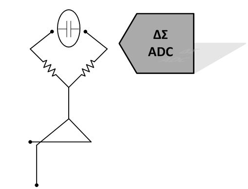
Figure 1: Anti-aliasing filters can kick back and relax in front of delta-sigma ADCs
ADC Architecture: SAR vs. delta-sigma ADCs
We now know that an ADC must sample the input signal slightly faster than the Nyquist rate to properly represent it in the digital domain. Before you begin designing your anti-aliasing filter, you must first understand the architecture of the ADC that it’s used for. This will dictate how close to the Nyquist rate your ADC will convert and therefore the response your filter needs.
Successive approximation register (SAR) ADCs sample the input at a frequency, fS, that is typically just beyond the required Nyquist rate. Frequency signal content begins to repeat at the Nyquist frequency (fS/2), so, to be effective, a SAR ADC’s anti-aliasing filter must have a sharp, high-order roll-off just before the Nyquist frequency to prevent any signals from aliasing. Creating this kind of response often requires using operational amplifiers as active filters, perhaps in multiple stages, which can be very challenging and expensive to design.
Oversampling data converters like delta-sigma ADCs sample the input much faster than the Nyquist theorem requires. Not only does oversampling push the delta-sigma ADC’s quantization noise away from the bandwidth of interest, it also moves the Nyquist frequency further away and allows for a more gradual anti-aliasing filter roll-off.
Figure 2 below illustrates the difference in the anti-aliasing filter response needed for a SAR ADC (Figure 2a) versus a delta-sigma ADC (Figure 2b).
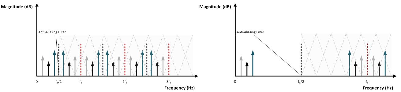 Figure 2a: Anti-aliasing filter response for SAR ADCs Figure 2b: Anti-aliasing filter response for delta-sigma ADCs
Digital decimating filter
What really sets the delta-sigma ADC apart, however, is the digital decimating filter. In delta-sigma ADCs, the input sampling rate is not the same as the output data rate! As the delta-sigma ADC’s modulator (over)samples the input at the frequency, fMOD, the data is decimated and passed through a digital filter before being output at a much slower data rate, fDR. The ratio of fMOD to fDR is known as the oversampling ratio (OSR). The higher the OSR, the more separation between fMOD and the passband. Many of TI’s delta-sigma ADCs allow you great flexibility in choosing an OSR that meets your application needs. For example, in the ADS1262, you can set the OSR as low as 24 or as high as 368,640!
The passband of the digital filter ends around fDR/2 or earlier depending on the filter’s frequency response. In between the passband and fMOD is a lot of unwanted signal content that could alias into the passband, such as the quantization noise from the modulator. This is where the digital filter really shines. The stopband of the digital filter provides significant attenuation from fDR/2 all the way until fMOD where the filter response repeats.
With the digital filter in place, the requirements placed on the anti-aliasing filter become even more relaxed! Instead of needing to filter everything beyond the Nyquist frequency as in SAR ADCs, the anti-aliasing filter for delta-sigma ADCs only needs filter out unwanted frequency content around multiples of fMOD. This allows for an even more gradual filter roll-off that is much easier to design with a few discrete, passive components. Typically, a single-pole RC filter is all that is required, but you may need a second-order filter for lower OSRs.
Figure 3 shows the filter response for a third-order sinc filter. As you can see, the digital filter is supplemented by the anti-aliasing filter to achieve an overall response with low in-band noise and very little signal aliasing.
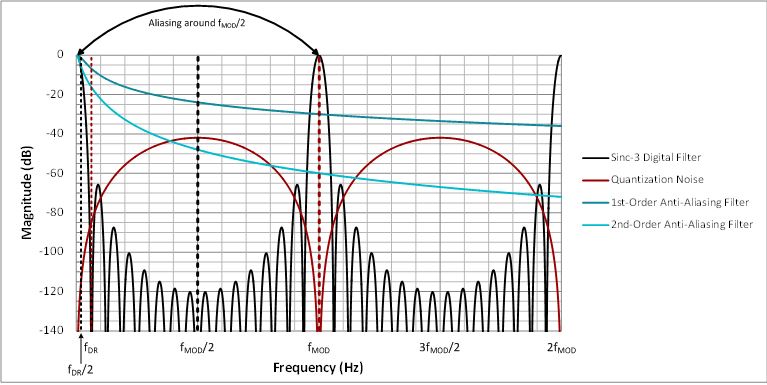
Figure 3: Combined responses of anti-aliasing and digital filters
In next month’s post, I’ll introduce several key guidelines to help you design the anti-aliasing filter that’s right for your application.
Additional resources
- Check out other posts by my colleagues with design tips and delta-sigma ADC basics, including one I wrote on aliasing in ADCs.
- Find more than 100 data converter technical resources in our Data Converter Learning Center.
-

Ryan Andrews
-
Cancel
-
Up
0
Down
-
-
Reply
-
More
-
Cancel
Comment-

Ryan Andrews
-
Cancel
-
Up
0
Down
-
-
Reply
-
More
-
Cancel
Children