

In part three of our Understanding Voltage References series, my colleague Marek Lis talked about how to achieve shunt reference flexibility with series reference precision. In this blog, you’ll see how to use an adjustable shunt reference as a comparator.
 Figure 1: TLV431 as a comparator
In a typical adjustable shunt reference application, the output is fed through a resistor divider to the feedback pin, such that the feedback pin is equal to the internal reference voltage during steady state.
In the schematic shown in Figure 1, the TLV431 adjustable shunt reference is configured for open-loop operation, which means that the output is not connected to the feedback pin. Instead, the signal VX drives the feedback pin through a resistor divider. The resistor divider is set such that the value at the feedback pin is equal to the internal reference voltage when VX is at the threshold voltage, VTH.
This configuration is similar to running an op-amp in an open loop, and driving the positive terminal with VX. However, instead of having to create a reference with another supply or a resistor divider for the negative terminal, the comparator reference voltage is internal to the part.
The output VOUT is driven high to VIN when the internal reference voltage is less than the threshold voltage, and is driven low when the internal reference voltage is greater than the threshold voltage. These conditions are summarized in Table 1 and illustrated in Figure 2.
Table 1: Conditions of Voltage Reference Comparator Output
|
VOUT Value |
Conditions |
|
VOUT = Vin |
VX < VTH |
|
VOUT = low |
VX > VTH |

Figure 2: Output of TLV431 Comparator Circuit
The output does not reach 0V on a logic low, because there is a minimum voltage drop across the shunt. For the TLV431, logic low in this comparator configuration is approximately 1V. The output of the comparator could be fed into another circuit to compensate for communication with various logic levels. A resistor divider on VOUT would be a very simple means of dropping the logic levels, but the impedance of the resistors should be high enough to not have a significant impact on the current into the shunt.
As an example, if we want a comparator with a threshold at 5V with a VIN of 12V, select an RS to sufficiently provide the minimum operating current for the selected device. For an input voltage of 12V, a supply resistor of 20kΩ will provide 600μA, which is more than enough to power the device that has a typical minimum operating current of 55μA. The resistor divider on VX to set the threshold voltage can be calculated from the following equation:
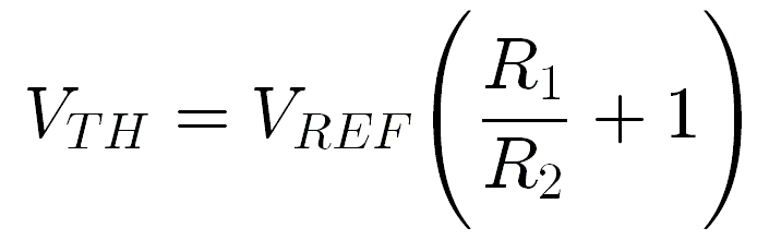 In this case, VREF is 1.24V and VTH is 5V. This results in a relationship between R1 and R2 where R1 ≈ 3R2. Figure 3 shows the schematic with values.

Figure 3: TLV431 as a comparator with 5V threshold
To sum this up, voltage references can be used for more purposes than for a simple fixed reference. This post demonstrates how a shunt voltage reference can act as a comparator. Coming up in the next post in the series, Understanding Voltage References, my colleague Marek Lis will discuss level shifting of precision voltage references.
For an overview of the difference between a series and shunt voltage reference, read Part 1: “Shunt versus series: Which voltage reference topology is right for you?"
In the meantime, get more more information on TI’s voltage reference products.

-

jun yin
-
Cancel
-
Up
0
Down
-
-
Reply
-
More
-
Cancel
Comment-

jun yin
-
Cancel
-
Up
0
Down
-
-
Reply
-
More
-
Cancel
Children