

Low-power applications such as e-meters often require a simple offline power supply, where 3.3V powers up a microcontroller and charges a lithium-ion battery to 4.2V. You can do this with a mains frequency power transformer or with a complex AC/DC offline power supply. Both approaches have well-known disadvantages related to weight, size and/or complexity. Two simpler options are full-wave and half-wave capacitor-drop circuits.
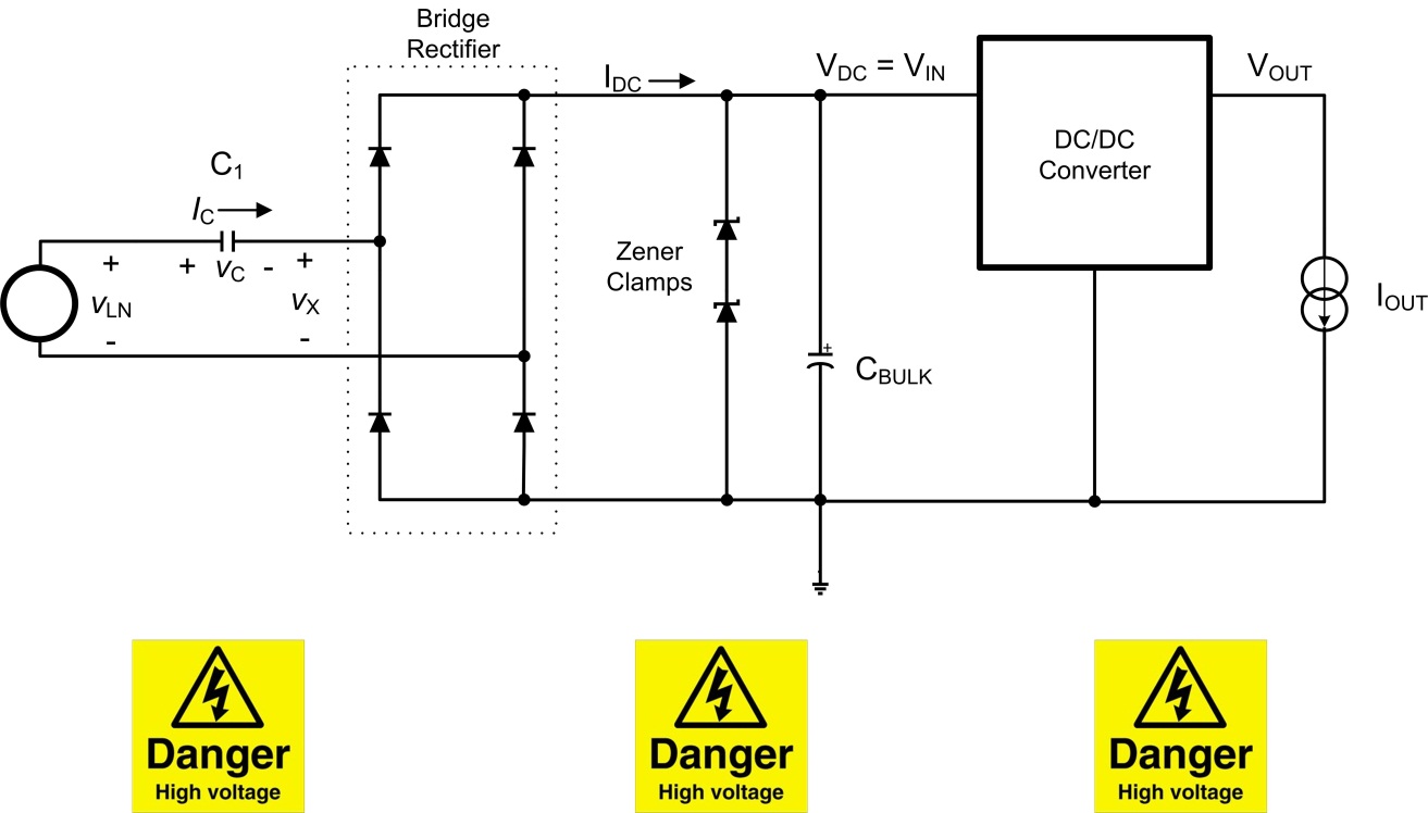
Figure 1: Basic full-wave schematic
The front end is the well-known “capacitive-dropper” or “cap-drop.” The idea behind both the full-wave and half-wave implementations of this circuit is that the line capacitor, C1, acts as a lossless resistance and the reactance of the capacitor will set the maximum current that can be provided to the input of the DC/DC regulator. The Zener diodes clamp the input voltage to the DC/DC converter under no-load conditions, thus converting the mains voltage to an intermediate DC rail (VDC). The input voltage to the DC/DC converter (VDC = VIN) is set to a relatively high value so that the current required from the cap-drop can remain low. You can then down-convert the intermediate unregulated DC rail (VDC) to the regulated DC voltage required by the load by using a wide VIN buck regulator.
The high step-down ratio, possible with devices such as TI’s LMR14006, LMR16006 and LM46000 buck regulators, allows for a lower input current to the regulator. This enables you to use a smaller value of C1, resulting in lower apparent power drawn from the mains. Applications such as smart grid e-meters can benefit from this feature because of strict regulations on the maximum apparent power consumption; the typical maximum is limited to 8VA.

Figure 2: Basic half-wave schematic
Figure 2 shows the implementation with a half-wave cap-drop circuit. Since the half-wave circuit will disregard the negative cycle of the line voltage, this will result in a lower current delivered to the input of the wide VIN buck than in the full-wave circuit. Thus, for applications like battery charging, where a faster charge would require a relatively higher load current from the DC/DC regulator, the full-wave circuit is preferable. In Figure 1, the full-wave schematic shows the implementation with the bridge rectifier.
The biggest advantage of these circuits is the size. In recent years, smart grid e-meters have been shrinking in size, making board space very constrained. To try and install a more conventional AC/DC circuit would not only increase the PCB area but would also be quite complicated. This increase in board area would also directly relate to the cost. Cap-drop circuits are much more cost-effective, as the C1 capacitor is the only component required to be rated for AC voltages.
While these circuits are easy to configure, you should take utmost care to create a bench prototype and add an appropriate filtering and protection circuit to avoid potentially fatal injuries.
Additional resources
- Read the application notes “Cost Effective Transformer-less Offline Supply for Light-Load Applications” and “Cap Drop Offline Supply for E-Meters”
- Download the Cap-Drop Offline Power Supply for Standard-Compliant Feature-Rich E-Meters TI Design reference design
- Learn more about TI’s smart grid and energy products
- Consider using TI’s LMR14006, LMR16006 and LM46000 buck regulators in your next design
- Start a power-supply design in WEBENCH® Power Designer
