

With the many advantages of using shunts as current sensors, they are often the current sensor of choice for metrology systems.
But as we saw in the previous entry in this series, the lack of isolation provided by a shunt inhibits its use in polyphase measurement. In three-phase star systems, based on Kirchhoff's Circuit Laws, the neutral current is the sum of all three line currents. Therefore, placing a shunt between the Live_In and Live_Out connections is the only way to measure the current of an individual phase. If all three phases are connected in this way it would lead to destructively high voltages being present across the pins of the measurement device.
To address the complications of using shunt sensors for poly-phase metrology systems, we recently published a new TI Design reference design that demonstrates a three-phase metrology system with isolated shunt current sensors.
This new TI Designs reference design, TIDA-00601, uses the AMC1304M05 reinforced isolated delta-sigma modulator with integrated LDO and the ultra-low-power MSP430F67641 microcontroller (MCU) for designing a Class 0.5% three-phase energy measurement system with galvanically isolated shunt current sensors. The block diagram of this reference design can be seen below.
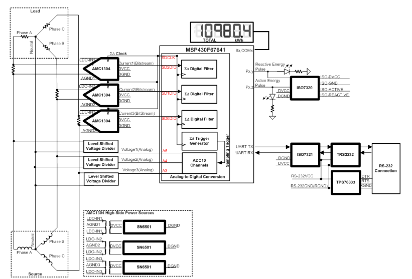
Figure 1: TIDA-00601 Block Diagram
In this design, the AMC1304M05 modulator’s voltage input range allows the voltage drop across the shunt to be accurately measured without the need for external gain amplifiers. The bitstream output of each AMC1304M05 is isolated with respect to the analog input. Specifically, the isolation barrier of the device is certified to provide reinforced isolation of up to 7000 VPEAK, according to the DIN V VDE V 0884-10, UL1577 and CSA standards. The working insulation voltage of up to 1.0-kVAC RMS allows the input of each AMC1304M05 to be connected to a different live line while the digital bitstreams of the modulator share the same ground reference. This feature enables current sensing without any hazardous voltages being present on the measuring device.
Once the AMC1304M05 modulators output their corresponding bitstreams, the MSP430F67641 MCU takes the data from each phase sensor and uses its integrated digital filters to obtain current samples for each phase. Simultaneously, the MCU uses its internal SAR data converters to obtain voltage samples for each phase. Using the voltage and current samples for each phase, the MSP430F67641 calculates the following parameters: active and reactive power and energy, RMS current and voltage, power factor and line frequency.
The metrology parameters can be viewed on the on-board LCD or via the PC calibration GUI tool. When the PC calibration GUI option is selected for viewing metrology parameters, the metrology parameters are sent from the board to a PC via RS-232. Through the use of the ISO7321 the RS-232 connection provides up to 3 kV of isolation, which allows PC GUI operation even when the board is connected to Mains.
Since only the basic features of this design has been discussed, if you want more information about this design please view the TIDA-00601 TI Design reference design and watch the video below. Also, to learn more in general about TI technology in metrology systems, please visit www.ti.com/metering .
Additional resources:
- Download the Multi-phase Energy Measurement with Isolated Shunt Sensors Reference Design
- Learn more about shunt sensors in this training video
- Did you miss the first two posts in this series? Check them out here:
