

Heat-cost allocators (HCAs) are intelligent electronic devices which are used to measure the amount of heat energy used by individual units in multi-dwelling buildings which use a centralized, radiated heating system. This measurement is used to allocate the overall cost of operating the central heating system.
HCAs are probably the “simplest” (in terms of functionality) sub-metering devices on the market and have very low power budgets: only a few microamperes on average. The microcontroller (MCU) in an HCA typically runs a real-time clock (RTC); controls a low-power segment LCD (often with 50-100 segments); takes regular readings of two temperature-sensing elements; and periodically runs RF transmissions, which broadcast the latest HCA reading and other data. Quite often, a bidirectional infrared (IR) communication port enables the connection of a mobile reader unit to an IR port in order to read or write data to the HCA unit.
The most important design considerations for an HCA
As with every high-volume application the unit cost (including both the bill of materials [BOM] and the manufacturing cost is an important design consideration. A system design which consumes the lowest energy will reduce the size of the battery required for the lifetime of the product and reduce that system cost.
Implementing the relatively simple HCA functions I listed above becomes much more challenging when all of them need to run for 12+ years on a single primary lithium thionyl chloride or lithium manganese dioxide cell battery, with capacities in the range of 900mAh to 1.2Ah. Achieving such battery lifetimes requires a highly optimized hardware and software design focused on ultra-low power for each and every function of the HCA. For example, an integrated SAR ADC (if a low-power ADC block is available) can measure temperature of a NTC element or LMT70A CMOS sensor; so could a slope conversion with an analog comparator, as shown in the application report, “Implementing an Ultralow-Power Thermostat with Slope A/D Conversion.”
The early HCA products were based on a two-chip solution: an ultra-low-power MSP430™ MCU and a RF phase-locked loop (PLL), something that we call a first-generation HCA. Second-generation devices use even more advanced MCUs (such as flash or the FRAM-based MSP430 MCU), together with an integrated RF transmitter device such as TI’s Sub-1 GHz CC115L or CC1175 solutions, or just the single-chip CC430 MCU with integrated RF.
While bidirectional RF communication is not mandatory for HCAs, it is sometimes used based on proprietary RF protocols for passing data from one HCA to another. With the European wM-Bus standard (EN13757-4) in place since 2005, many metering and sub-metering HCA products on the market today use wM-Bus as the RF protocol, although many proprietary protocols still exist at the 433MHz and 868MHz ISM frequency bands.
Some vendors offer multiprotocol HCAs supporting their own proprietary RF protocol in parallel with the popular wM-Bus S, T and C modes. In such cases, the flash/FRAM size and RAM resource demand in the application increase significantly. FRAM-based MCUs such as the MSP430FR9672 MCU family can dynamically move the partitioning between the program code size and RAM size, thus offering some cost advantages versus flash-based MCUs, which would require the next bigger memory derivative.
TI has been a pioneer in the HCA market for more than a decade, with the MSP430F4xx series setting the bar for performance and MCU ultra-low power consumption. With the significant improvements in available MCU products in the last five to six years, also ARM-based MCU architectures with flash technology can now meet HCA power and system requirements.
TI recently introduced several reference designs with FRAM-based MCUs for the HCA market. These are second-generation-type designs. The Matched Precision Temperature Sensing Reference Design for Heat Cost Allocators (TIDA-00646) analyzes the temperature measurement subsystem and offers a new approach by replacing the traditional NTC sensors with high-precision matched analog CMOS sensors (LMT70A).
The Flash-based SimpleLink™ Sub-1 GHz CC1310 wireless MCU uses an integrated ultra-low-power sensor controller peripheral, including a SAR ADC12 block, to power on and read out the LMT70A sensors with a minimal power budget.
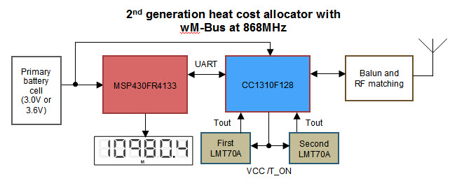
Figure 1: TIDA-00646 and TIDA-00838 block diagram
Using the same PCB as the Matched Precision Temperature Sensing Reference Design for HCAs, the Heat Cost Allocator with wM-Bus at 868 MHz Reference Design (TIDA-00838) extends the software implementation further for HCA systems following the EN834 standard with the two-sensor measurement method.
Both reference designs achieve better than 0.5°C accuracy across a range of +20 to +85°C without any calibration, even while using unmatched (LMT70) temperature sensors. Using the LMT70A (the matched CMOS temperature sensor version) completely eliminates the need for calibration during manufacturing and lowers manufacturing costs. The CC1310 wireless MCU offers also wireless wM-Bus support for S, T and C modes (meter devices) at 868MHz, with the open-source code example available for download.
The MSP430FR4133 MCU runs the HCA application code and RTC and controls a 96-segment LCD, which is always on. All of these tasks, including periodic RF transmission of a wM-Bus telegram, require less than 3.2µA with the segment LCD display switched off and temperature sensing every 4 seconds (4 seconds is more frequent than usual in the field).
What is the future for HCAs?
Recent developments in semiconductor technology indicate that third-generation HCA devices will be a single-chip solution with even lower power consumption, allowing further reduction of the battery size and possible integration of the XTALs (a sleep mode with 32.768kHz or RF system clock with 24MHz) for additional BOM cost reduction. Some total cost savings (less so in the BOM) are possible through the integration of passive components for the Balun and RF matching parts, which enable simpler and faster design and manufacturing. Some future HCA products may even use a dual-band solution that offers a Sub-1 GHz and a Bluetooth® low energy protocol connection for much more convenient readout and configuration through a Bluetooth® low energy-enabled smartphone or tablet.
Even with the associated additional cost, new RF communication technologies might help reduce the total cost of ownership for HCAs. Increasing HCA unit cost to support long-range protocols for the Internet of Things (IoT) (such as SIGFOX) will be offset by larger cost reductions for building and maintaining infrastructures for automatic reading and billing. Typically, such infrastructures include multiple battery-powered gateways (or data collectors), which communicate among themselves and aggregate the readout values for delivery to the back office. SigFox technology can be a suitable option to change readout in millions of HCA units deployed today.
While the Heat Cost Allocator with wM-Bus at 868 MHz Reference Design (TIDA-00838) is an excellent HCA solution, the cost of two MCU devices is higher than one. In order to enable a third-generation HCA solution, TI has developed an innovative patent-pending solution where the addition of a few resistors and optimized GPIO control software adds segment LCD functionality. Such a GPIO-driven solution for segment LCD is really useful in any application where a segment LCD is required but does not have to always be on. This is the case for many HCAs and water and heat meters, thermostats, and various other IoT applications. The LCD display itself is switched off most of the time and activates only when required, as the current consumption in the reference design for the software approach is in the range of 300µA when the LCD is enabled (or visible).
The sensor controller core checks every second for a touch event at the small circular area next to the antenna connector (see Figure 2) in order to activate the LCD. The CC1310 average current is 644nA (with the capacitor touch sensor task running), even when the LCD is off.
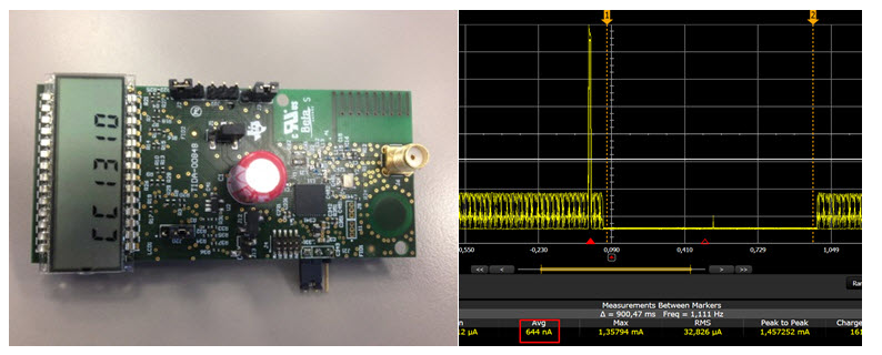
Figure 2: TIDA-00848 with LCD enabled and current consumption in sleep mode
TI’s solution for third-generation HCA is here now – just go get it.
Additional resources
- Check out the TI Designs Reference design for Segment LCD Control Using GPIO Pins to Increase System Flexibility.
- See new designs on TI's smart grid solutions overview.
