

I posed a question a couple of weeks ago regarding film capacitors—what’s the meaning of the stripe on one end? Check the picture below.
These are non-polarized capacitors so it’s not a polarity marking. A reader, Richard, answered correctly—it identifies the outside conductive foil of the spiral wrapped innards. I’m finding that few engineers these days know this, and proper orientation can make a difference. Even if you never use one of these caps, it may cause you to design your PCB layouts differently. Let’s think about it.
The outside foil of a spiral-wrapped film capacitor shields the inner conductor. In a simple low-pass R-C circuit, figure 1a, one side of the capacitor is grounded so it makes good sense to connect the striped end to ground to shield the signal side from electrostatically coupled interference.

What about the high-pass case, figure 1b? Neither side of the capacitor is grounded. But generally, the previous stage driving this circuit (perhaps the output of an op amp) is a low impedance that would be less susceptible to induced noise. So connect the stripe to the low-Z side.
Now, what to do with the integrator circuit, figure 2a? The output side of the integrator capacitor is driven by the low impedance of the op amp and is not easily perturbed by external interference. The inverting input is clearly the more sensitive node. The stripe should go on the output side of the op amp.
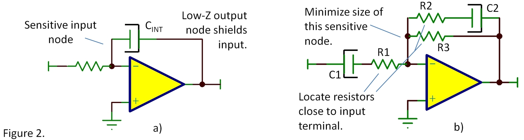
There’s more to consider in figure 2b. The order in which C1 and R1 are connected could make a difference. Same with R2 and C2. In theory, the order is irrelevant and SPICE simulations would show identical results. But R1 and R2 are physically smaller and can be located close to the inverting input terminal. This reduces the “antenna” area and capacitance on this sensitive node (which can affect stability). The physically larger film capacitor, C2, is located on the output side of the op amp with the stripe connected to the low impedance output terminal.
I mostly think about sensitive analog circuitry that could be susceptible to interference but you may have noisy circuitry that might be a source of potential interference. Again, careful placement and orientation may yield improvement. And this is not just about striped capacitors. There may be other large components in your system that can be a source of noise pickup or radiation. With awakened awareness you may find other opportunities for tweaks and improvements to your PCB layouts.
Striped capacitors are but a quirky reminder that there’s a lot to know about good circuit board layout—grounding, signal routing, component selection and placement. Many of our data sheets have very specific information that can help optimize performance. And here are a few links to general ideas for improved layouts:
- Reducing PCB design costs: From schematic capture to PCB layout
- PCB Layout Tips for High Resolution—Section 9
- High Speed Amplifier Layout Tip—general tips also applicable to precision analog circuits
- PCB Design Guidelines for Reduced EMI—Reduction of EMI in microcontroller circuitry
Thank for reading, and comments are welcome!
Bruce email: thesignal@list.ti.com (Email for direct communications. Comments for all, below.)
Table of Contents for all The Signal blogs
-

Ron Vinsant
-
Cancel
-
Up
0
Down
-
-
Reply
-
More
-
Cancel
Comment-

Ron Vinsant
-
Cancel
-
Up
0
Down
-
-
Reply
-
More
-
Cancel
Children