This thread has been locked.

If you have a related question, please click the "Ask a related question" button in the top right corner. The newly created question will be automatically linked to this question.

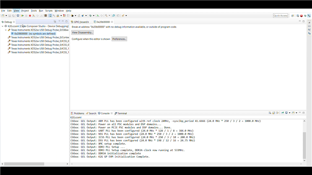
[FAQ] EVMK2G: How to run GPIO Examples for DSP core on K2G EVM

Part Number: EVMK2G

How to do build, run and test the K2G GPIO example projects in the DSP core from TI-RTOS SDK?

  • To run the GPIO example for K2G devices make sure the prerequisites are present.

    1. Install CCS (https://www.ti.com/tool/download/CCSTUDIO/9.3.0.00012),
    2. TI RTOS SDK
      1. For K2G: Install PROCESSOR-SDK-RTOS-K2G  (Version: 06_03_00_106, https://software-dl.ti.com/processor-sdk-linux/esd/K2G/latest/index_FDS.html ),
    3. Generate the Example projects for PDK,
      1. For K2G: https://e2e.ti.com/support/processors-group/processors/f/791/t/1135633.

    Now, Import the CCS project into CCS and go on

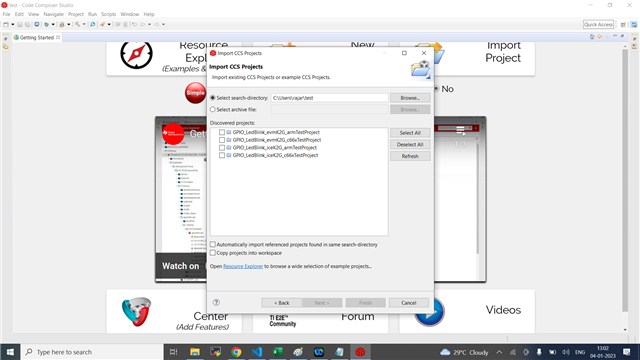
    1. To Import the project, Goto File -> Import -> "CCS projects" in "C/C++" -> Browse "Select Search-directory". make sure to uncheck the "Copy Projects into Workspace" (This is to avoid compilation errors only If TI-RTOS SDK was installed in a different location than "C:\ti\").

      1. we have the following DSP example projects

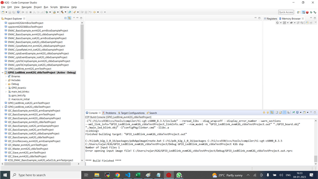
        1. GPIO_LedBlink_evmK2G_c66xTestProject,

        2. GPIO_LedBlink_iceK2G_c66xTestProject.

      2. Do not open ARM and DSP examples at the same time, CCS will throw the project out-of-sync error dialog.

    2. For Hardware connections,

      1. we can connect through Mini USB connecting through J1 (Another mini USB port (J3) used by Onboard Debug Emulator).

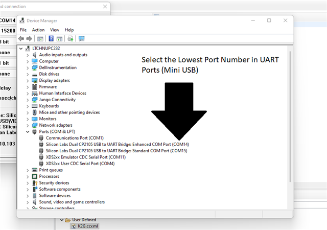
      2. There will be two mini USB ports available for UART in the "Device Manager" section in "Windows OS" (CP2105 chipset, refer to device manager image for reference)

        1. The Port with the lowest number is the UART port.

        2. The Port with the highest number is BMC port.

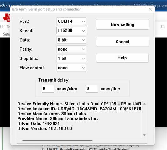
      3. UART configuration used in these projects were "8N1"(Data Bit = 8, Parity = None and Stop bit = 1) and baud rate "115200".

      4. To create a Target configuration for "EVMK2G" kindly refer to the URL https://e2e.ti.com/support/processors-group/processors/f/791/t/1135633

      5. No Boot switch settings are,

        SW3[4:1] BOOT MODE
        0000 (0x0) Sleep/No Boot
        0001 (0x1) PCIe boot
        0010 (0x2) Ethernet Boot
        0011 (0x3) I2C PLL Boot
        0100 (0x4) SPI No PLL Boot
        0101 (0x5) SPI PLL-1 Boot
        0110 (0x6) USB Boot
        0111 (0x7) MMC/SD Boot
        1000 (0x8) UART Boot
        1001 (0x9) QSPI 96 Boot
        1010 (0xa) eMMC Boot
        1011 (0xb) NAND Boot
        1100 (0xc) I2C No PLL Boot
        1101 (0xd) SPI PLL-2 Boot
        1110 (0xe) SPI PLL-3 Boot
        1111 (0xf) QSPI 48 Boot
      6. Hardware connection details are explained on this page https://software-dl.ti.com/processor-sdk-linux/esd/docs/06_03_00_106/linux/How_to_Guides/Hardware_Setup_with_CCS/66AK2G02_GP_EVM_Hardware_Setup.html

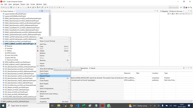
    3. To Build the project, Right click on the project and select "Rebuild project". Check for compilation errors and look for "Compilation finished successfully". 

    4. Load the memory in the DSP core 
    5. Kindly refer to the video demo 

    Thanks & Regards,

    Rajarajan U