This thread has been locked.

If you have a related question, please click the "Ask a related question" button in the top right corner. The newly created question will be automatically linked to this question.

OPA855: opa855

Part Number: OPA855
Other Parts Discussed in Thread: TINA-TI

Can someone explain the below concept, I'm not able to understand it!

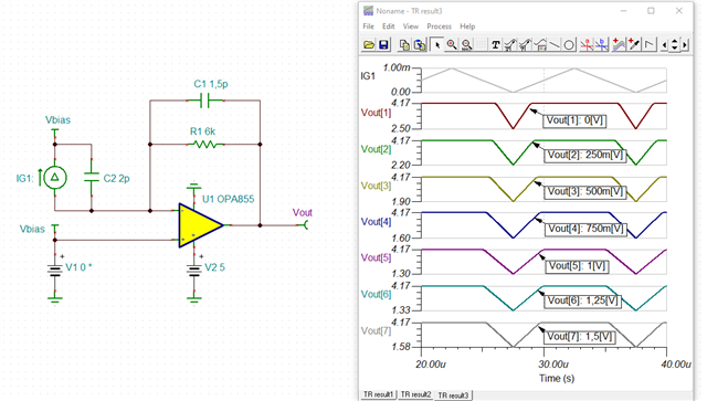
"TIA common-mode configurations With the PD configured as shown in Figure 3, the output of the TIA will swing in a negative direction relative to VCM_TIA. To maximize the output swing of the TIA, set VCM_TIA at the lower compliance limit of the TIA’s positive common-mode input voltage and its most positive output swing.

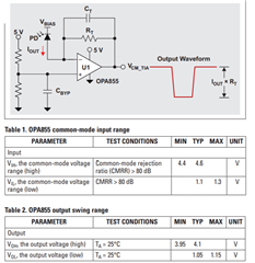
For example, in the case of the Texas Instruments (TI) OPA855, VCM_TIA should be set to 3.95 V when the amplifier is configured with a 5-V positive supply and a 0-V negative supply. See Tables 1 and 2. In this case, the maximum output swing is 3.95V–1.15V=2.8V.

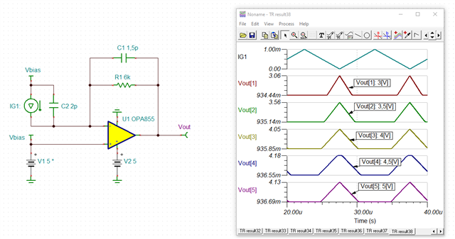
When configuring the PD as shown in Figure 4, the output of the TIA will swing in a positive direction relative to VCM_TIA. To maximize the output swing of the TIA, set VCM_TIA at the higher compliance limit of its negative common-mode input voltage and the TIAs most negative output swing.

For example, for the OPA855 (see Tables 1 and 2), VCM_TIA should be set to 1.3 V when the amplifier’s supplies are at 5 V and ground. In this case, the maximum output swing is 4.1 V – 1.3 V = 2.8 V."

Extracted from document-Maximizing the dynamic range of analog front ends having a transimpedance amplifier

  • Hello,

       This excerpt is referring to how to maximize the output voltage swing of the OPA855 when using the photodiode in either cathode or anode biased. If the photodiode is biased at the cathode, the voltage at the cathode should be higher than the voltage at the anode, so the photodiode sources current as shown in Figure 1. If the photodiode is biased at the anode, the voltage at the anode should be lower than the voltage at the cathode, so the photodiode sinks current as shown in Figure 2.

       This means for Figure 1, the voltage at the output of the amplifier will be in the negative direction as shown in Figure 3 example waveform. And for Figure 3, the voltage at the output of the amplifier will be in the positive direction as shown in Figure 4.

        For a split supply design, this would not be too much of an issue in regards to output swing. But for single supply as shown in this example, then you would need to bias this output voltage or in other words apply a DC voltage to the output signal. This can be done by applying a DC voltage at the non-inverting input of the amplifier.

        Since photodiodes are unipolar at usually a DC bias of 0V, then the common-mode voltage (DC bias) should be set to the the opposite of the direction of the output voltage. For Figure 3, this would be at the maximum output voltage of the OPA855. This will give the highest output voltage swing possible out of the OPA855 which is 2.8V. For Figure 4, this would be at the minimum output voltage of the OPA855. This will also give the highest output voltage swing possible out of the OPA855 which again is 2.8V.

        Let me know which part I might need to add more clarification.

    Thank you,
    Sima

  • Hi Sima,

    Could you pls clarify on the calculation specified. 

     To maximize the output swing of the TIA, set VCM_TIA

    1)at the lower compliance limit of the TIA’s positive common-mode input voltage and its most positive output swing. 3.95V–1.15V=2.8V -Is it output range  3.95V Voh and 1.15V Vol?

    2)at the higher compliance limit of its negative common-mode input voltage and the TIAs most negative output swing.4.1 V – 1.3 V = 2.8 V - Is it input range Vil 1.3V and Voh 4.1V?

  • Hi Viny,

    why not running a TINA-TI simulation?

    Kai

  • Hi Kai,

    Im trying to learn the concept first then do the simulation.

  • Thank you for the simulations Kai! Helps explain the concept much better.

    Hello Viny,

      Yes you are correct for your statements: 1) and 2). 

    Thank you,

    Sima