This thread has been locked.
If you have a related question, please click the "Ask a related question" button in the top right corner. The newly created question will be automatically linked to this question.
Hello team,
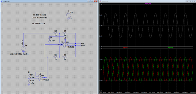
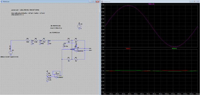
Can you show me the designed values for the below requirement?
[Requirement]
・Input voltage: 1Vpp Sin signal (DC2.5V)
・Output voltage: sin+:Same as input signal / sin-:DC2.5V, AC is inversion signal of sin+
Best regards,
Shotaro
Hello Shotaro,
Would you be able to clarify the application.
Also, what is the bandwidth of the input signal?
Any need for filtering?
What is the load at the output of the amplifier?
Thank you,
Sima
Hello Sima,
The below is answer for your question.
Would you be able to clarify the application
->Sensor for elevator motor
Also, what is the bandwidth of the input signal?
->6.66...Hz
Any need for filtering?
->No need
What is the load at the output of the amplifier?
->Resistor to receive the receiver at the I / F of the driver for the elevator motor
The customer is considering the below circuit, but due to the board space, they want to reduce the buffer (U3: TLV9052).
What do you think about this?
Best regards,
Shotaro
Hello Sima,
I have an update for my comment in blue.
Would you be able to clarify the application
->Sensor for elevator motor
Also, what is the bandwidth of the input signal?
->6.66...Hz
Any need for filtering?
->They need 3rd LP filter (bandwidth: 284kHz).
They simulated it with the below schematic, but the output signal is small than their output target.
What is the load at the output of the amplifier?
->Resistor to receive the receiver at the I / F of the driver for the elevator motor
Best regards,
Shotaro
Hi Shotaro,
R5, R6 and R7 are way too high and they destroy the balance of your THS4532 circuit.
Why are you needing a differential output at all?
Kai
Hi Kai,
Can you optimize these value (R5, R6, R7)?
They use THS4532 circuit as 2ch line driver.
Best regards,
Shotaro
Hi Shotaro,
what is driving the THS4532 circuit? What output impedance has this driver? Is it an OPAmp or is the THS4532 directly connected to a shunt?
Low pass filtering is usually performed in the feedback loop of THS4532 itself, as shown in figure 89 of datasheet.
You cannot dismiss the 2.5V voltage source biasing the THS4532.
Kai
Hello Shotaro,
Is there an update for Kai's questions? The most important aspect is the balancing of the FDA, as well as the filtering method that Kai pointed out. A low pass MFB topology is popular method for these types of applications.
Thank you,
Sima