A related question is a question created from another question. When the related question is created, it will be automatically linked to the original question.
If you have a related question, please click the "Ask a related question" button in the top right corner. The newly created question will be automatically linked to this question.
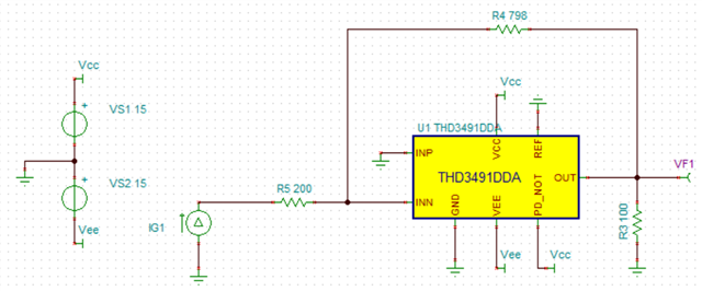
As for CFA, why do you choose a voltage source rather than a current source? If I want the closed loop gain, I think it's Zcl rather than Acl. Am I right? Please give some guidance. Thanks for your help!
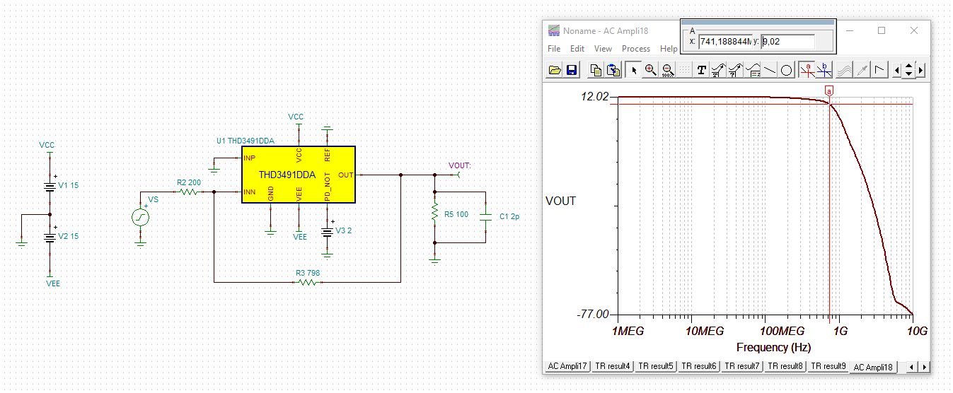
I am confused about F-3dB. We regard F-3dB as BW, but in which picture can I observe the F-3dB? How to simulate that picture? In my view, the picture is the closed loop gain of CFA. When simulating, which source should I choose, voltage source or current source? Which terminal should I put the source, inverting terminal or none inverting terminal?