This thread has been locked.

If you have a related question, please click the "Ask a related question" button in the top right corner. The newly created question will be automatically linked to this question.

OPA455: how to increase output current

Part Number: OPA455
Other Parts Discussed in Thread: OPA551, OPA462, INA228, OPA2192, TINA-TI, OPA454, OPA1622

Hello  TI expert

1.There is a piezo driver project need to design, below is the piezo actuator information

the  capacitors min is 0.15uF and max is 15uF, the resonant frequency is between 40Khz to 135Khz,

maximum power consumption is between 0.8W to 34W, maximum travel range: At 0 to 120 V, The decice

current is calculate Imax =Pi *f* C*Uvpp.

2.A ccording above, If choose the OPA455 driver a device capacitors is 3.1uF, voltage is 100V the maximum frequency is 46Hz.

If increase the frequency the OPA455 cannot achieve, it may be need  extend the current to achieve.

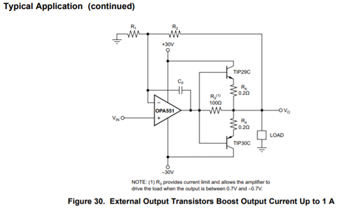
3.My question is how to use OPA455 extend the current or other solutions? Can you suggest some typical circuit ? If the

circuit  can select output sine wave, square wave or triangular wave is the best.

  • Hi,

    The OPA455 HV op amp can readily output about +/-30 mA to +/-35 mA, but can't be expected to provide much more because the short circuit current is typically +/-45 mA. Therefore, something more need to be applied if higher current is required by a load.

    There are power op amp application circuits where two, and sometimes more op amps are arranged for parallel outputs increasing the output current capability over a single op amp. Often, these circuits work better on paper than in reality because of output current imbalances between each op amp being applied. Much of the difficulty stems from the different voltage offset each op amp has. Then, there are thermal imbalances between devices that can complicate the current sharing between them.

    Rather than suggesting the parallel outputs approach I suggest adding a bipolar output stage to increase the OPA455 output drive capability. Although the OPA455 datasheet doesn't show such a circuit, another high-current op amp, the OPA551 shows this in its datasheet. I've included the circuit from the OPA551 datasheet here:

    This is a lower voltage circuit than what the OPA455 may be applied to, but the TIP29C and TIP30C transistors and associated components should be applicable. The transistors are good for a 100 V collector-emitter voltage, and 1 Ampere of collector current. Since the electrical conditions are different for the OPA551 shown, and the OPA455 is a different op amp I expect some design changes and experimentation would be required to arrive at a circuit having satisfactory performance.

    Regards, Thomas

    Precision Amplifiers Applications Engineering 

  • Hello  Thomas

    Thank you for your quickly reply,

    1.According your advice I update the schematic ,please kindly review the schematic .

    2.I am still have some questions want to ask you

    1. What is the different between OPA455 and the OPA462? The OPA455 show the Wide power-supply range:±6 V to ±75 V or

    12 V to 150 V, but the OPA462 is  ±6 V (12 V) to ±90 V (180 V), so the OPA462 can power by 12V- 180V? or can OPA462 replace

    OPA455?

    1. Because need to monitoring the current , and the common voltage is too high, I didn’t find the fit current sensor OP,

    So I series two resister,and INA228 to measure the current, so it can work well?   

    01_source.pdf

  • Hi,

    There a couple of issues with your schematic:

    1. The DAC1 upper op amp has a 2.5 V DAC input and the resistors set up a gain of 1 + 39.2 k/10 k, or about +5 V/V. Therefore, the output voltage will be +12.5 V at REF10V.
    2. The DAC 0, 0.25 V to 2.5 V input applied to the OPA2192 buffer, will apply that same voltage range to input of the OPA455 in the power amplifier stage. The OPA455 minimum common-mode voltage is specified as +1 V above the negative supply rail. That would be a problem.
    3. It is not clear what you are doing capacitively coupling the REF10V output with output form the OPA455 power amplifier. If the power amplifier is producing an ac waveform it will be coupling that signal directly into the output of the REF10V OPA455.
    4. I see how you have integrated the TIP29 and TIP30 power transistors into the OPA455 amplifier circuit. The arrangement looks okay, but I suggest testing the circuit in a simulator such as TINA-TI to better evaluate the dc operating points, and the ac behaviors. It is hard to know if the arrangement will be ac stable without a simulation.

    Regarding your questions:

    1. What is the different between OPA455 and the OPA462? The OPA455 show the Wide power-supply range:±6 V to ±75 V or 12 V to 150 V, but the OPA462 is  ±6 V (12 V) to ±90 V (180 V), so the OPA462 can power by 12V- 180V? or can OPA462 replaceOPA455?

    The OPA455 and OPA462 are similar and are in the same HV family. If your application needs to be able to withstand the higher voltage that the OPA462 specifies then you should be able to receive very similar electrical circuit performances to that had from the OPA455.

    2. Because need to monitoring the current , and the common voltage is too high, I didn’t find the fit current sensor OP, So I series two resister, and INA228 to measure the current, so it can work well?

    The INA228 is produced by another TI organization and I am not familiar with the device; however, looking over the datasheet it looks like what you propose should work. I suggest making an inquiry to the TI Conversion products e2e forum and ask them for guidance in applying the device.

    Regards, Thomas

    Precision Amplifiers Applications Engineering

  • Hi Thomas

    Thank you for your advice. I will update the schematic late. I am sorry to the schematic that didn’t comment the part number.

    1.The REF10V series a 1R resister, I just want to add the protect function, the OPA455 integrated over current protect maybe it should remove 1R resister.

    2.Can you explain more about E/D and E/D COM pin function?

    3.There is a similar circuit https://e2e.ti.com/support/amplifiers-group/amplifiers/f/amplifiers-forum/911718/opa454-how-to-increasing-output-current

    4. attachment is the require wave form.

    wave.zip

  • Hi,

    Okay, on the high-voltage op amp circuit using the OPA454 and external transistors posted on the e2e. It looks like my colleague Raymond, and our friend Kai, were assisting with the design. I would stay with the TIP29 and TIP30 transistors because your output current requirements are not higher than an ampere. Since the OPA454 and OPA462 are quite different in design and have different electrical performances some component tweaks may be necessary, but the overall circuit they created should provide a good starting place.

    The OPA455/OPA462 E/D function is output Enable, or output Disable (shutdown). If for instance a user wishes to save power, the OPA455/OPA462 output can be disabled and the power drops by about 50 %. The E/D pin voltage is referenced with respect to the E/D common pin (E/D COM). The E/D COM pin voltage setting can be set over a wide voltage range to allow the user maximum design flexibility. For VS ≥ 106 V, the E/D COM voltage can be set from (V–) to (V–) +100 V, and for VS < 106 V it can be set to (V–) to (V+) – 6 V. Section 7.3.4, of the OPA455 datasheet, Enable and Disable, provides a good explanation of the function.

    I do think you should set up the circuit simulation as suggested earlier and apply the wave.zip waveform. This will give you an opportunity to see if the circuit output at the load is what you expect.

    Regards, Thomas

    Precision Amplifiers Applications Engineering

  • Hi  Thomas

    1.There is still  thermal characteristics need your help analysis . If the current is between 0-100mA, so how much the heat will create on TIP29C and TIP30C? How to select the heat sink?

    2.Can I use the sample formula  P = UI = 100V*0.1A = 10W on the power transistor?

  • Hi,

    I don't know what your exact power supply conditions will be for the OPA455 external output stage are, but do note that the worst case dissipation will occur when the output voltage swing is at one-half the DC supply voltage. Thus, if the OPA455 external output stage is powered by a +/-75 V supply and the output voltage is positive the worst case TIP29 dissipation occurs with a +37.5 V DC output. Likewise, the worst case TIP30 dissipation occurs when the output is -37.5 V.

    The power being dissipated in the output transistor with an output current of 100 mA is:

    PD = (Vcc/2) Io

    PD = (75/2 V) 0.1 A = 3.75 W

    That shouldn't be an issue for the TIP29 and TIP30 providing they are correctly heatsinked. 

    If the output is another DC level the dissipation will be down from that level. An AC signal is more complex and the power dissipation will depend on the particular waveform. There is a very nice power dissipation explanation provided in the 7.3.1, Power Dissipation, section of the OPA1622 audio op amp. It is completely different device than the OPA455 and external transistors, but the explanations and math are applicable to them.

    https://www.ti.com/lit/ds/symlink/opa1622.pdf

    Regards, Thomas

    Precision Amplifiers Applications Engineering