This thread has been locked.

If you have a related question, please click the "Ask a related question" button in the top right corner. The newly created question will be automatically linked to this question.

THS4561: ThS4561 Differential Amplifier - I am working on a Microphone design with the THS4561. Can Anyone take a quick look to see if I have done it right. I don't have much experience with fully differential designs

Part Number: THS4561
Other Parts Discussed in Thread: INA849, INA163, , TINA-TI, THP210

DSN10116.pdf

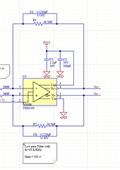
This is a small board, part of a clients larger project.  The output of the MIC is differential and has an impedance of 355 Ohms.  They are going to be sampling at 250KHz, about 10x over sample.  They don't really know how much gain they will need but expect the sound levels to be low. We decided to start with a gain of about 100.  I chose the 10uF DC blocking cap because it I think it will form a high pass filter at about 44 Hz which is just below the bottom end frequency of the mic. I put the 220pf cap in the feedback to form a 20Khz low pass for antialiasing.  I think the 715 ohm termination resistor will impendance match the mic to the amp.  They have a differential DAC that has an midpoint (zero) at 0.75V so I have the Vocm set to that voltage.

For those of you who have lots of experience with fully differential amplifiers, have I made the correct assumptions?  This is my fist time using one and I would like to get in the ballpark before making the board for the client.

Thank you for your help.

  • When the input signal is very low, as you said, I would take an amplifier which shows much less noise like the INA163 or INA849.

    Kai

  • Looks pretty reasonable so far, on the output side you say a DAC sample rate? do you mean an ADC sample rate, also, do you intend any RC at the ADC inputs from the FDA. 

  • Thanks Kai, but both of those amplifiers are differential to single ended and our customer specifically wanted a differential signal at their DAC board.

  • Yes, they plan to sample at about 250Khz on their ADC (Sorry- dyslexia flipped the letters). I believe they want to use these in a phased array so they need to sample high enough to get good resolution on the phase difference.  Unfortunately, I don't have access to the ADC.  Usually I put a low pass filter right in front of the ADC, as physically close as possible.  They may have to consider a custom design so we can do that, but for now they just want a differential signal.  I believe it will be twisted pair for about 15 feet from the microphone board to their ADC system.  Thanks for looking at it.

  • well really what I am after is your parasitic load capacitance, you know you can't drive that twisted pair directly without risking oscillations, and you are probably close already with the feedback cap - i just didn't want to work on fixing those issues until I had the full circuit - meaning the load. 

  • Actually I did not know we could not drive the twisted pair directly.  I thought that was a preferred method of transmission.  What should we use as a cable between the amp out and the ADC input?  The ADC is a commercial board and so we don't have the ability to design a filter on it. We might dead-bug a daughter board on it to put a lowpass filter at the input to the ADC. I can remove the caps on the differential amp if that is going to cause a problem.  Do I need a termination on both ends of the cable (THS4561 out and ADC input)?

  • Also, I discovered a mistake in the feedback. I think the positive output must go to the negative input and vice versa to be stable. I had the positive to the positive and negative to negative, but have fixed that now.

  • Does the ADC board have an input impedance spec? 

    Twisted pair can work, but to be sure some idea of the load on the FDA output is required included that cable C, some series R into the cable will probably be prudent

    The front page of the THS4561 shows one version of an Audio filter app that I was iterating on for awhile, The part can work quite well, but does need some phase margin focus. I have quite a lot of background info on stabilizing these part, but tha all depends on having the correct load. No reason to proceed without that. 

    But if you want to see where I am heading start with this Insight #5 then #8 is focused on FDA's for loop gain phase margin analysis. 

    https://www.planetanalog.com/stability-issues-for-high-speed-amplifiers-introductory-background-and-improved-analysis-insight-5/#

  • After looking into the datasheet of ICS40619 I want to withdraw my recommendation with the low noise INA163 and INA849. The ICS40619 outputs a noise floor of -105dBV in the 20Hz...20kHz band which is 5.6µVrms. This equals a noise voltage density of roughly 40nV/SQRT(Hz). So the 4nV/SQRT(Hz) noise of THS4561 plays no role at all.

    Kai

  • Hi Sean,

    if the customer has a 250kHz ADC, they should have the charge bucket filter directly at the input of ADC. And the buffer feeding this charge bucket filter should also sit directly at the ADC input. Having the buffer for the charge bucket filter in 5m distance apart from the ADC input sounds a bit unusual for a 250kHz ADC. In this case I would try to terminate the input of charge bucket filter with the cable impedance, in order to prevent the cable capacitance from ruining the performance of charge bucket filter.

    Can you find out what ADC setup the customer is using? Is there already a charge bucket filter on the ADC board? Is there already a buffer for the charge bucket filter or ADC input on the ADC board?

    What sort of twisted pair do you intend to use? Cat5? Cat6?

    Kai

  • I asked about how they plan on sampling the signals and they are going to use the MCC128 Stacked boards.  I could not find anything in the provided datasheet about onboard filtering. The input impedance of the board is listed as 1-Gohm.  With that input impedance, I am guessing it must be terminated or there will be a large reflection.

    Based on our conversation here, we are now planning to use twisted pair for the power and coaxial cable for the differential output of the 40619.

    I will add two series resistors on the output of the amp and we can try various values to match the cable impedance, which I don't' think we will know ahead of time.

    Thank you all for you help.

  • Hello Sean,

       The circuit looks good, but as mentioned from Michael, it is best to determine the loading the amplifier since it is a critical part to the overall stability of the system. I recalculated some of the values at the input stage for input impedance, and created a Tina-TI simulation attached below. Looks like it matches the design theory of passband between about 45Hz to 20KHz. Once RC filter and the input impedance of the ADC are finalized, it is best to include these in the simulation, and work out a stability analysis of the FDA. 

    THS4561_Sean.tsc

    Thank you,

    Sima 

  • Sima,

    Thanks for doing this analysis. It looks like we may have a stability problem.  I have added two series resistors to the board and we can use the pads to put one from Vo+ to Vo- if needed.  I am sending off the board to be made and will see how it works. Thank you.

  • Hi Sean,

    do you have such a MCC128 board at hand? Can you find out where each input line is going to? Is it an OPAmp input? Is it a multiplexer input? Or is it an ADC input?

    Kai

  • Hi,

    take a look at the THP210 full diff amplifier

    With best regards

    Gerhard