This thread has been locked.

If you have a related question, please click the "Ask a related question" button in the top right corner. The newly created question will be automatically linked to this question.

INA226: INA226AIDGST

Part Number: INA226

Hi 

We have used the INA226 part in our design but now; the layout and board assembled are done and we got one connection mistake like INA226 pin IN+ and IN- are interchanged on the resistor both ends for more clarity check the attached image.

As per image resistor end IN+ but as per application circuit require IN- so is it work or do we need to change ??

  • Hello Bhadresh,

    Thank you for the question and using the E2E forum.

    The short answer here is it depends. The INA226 can measure bidirectional current as long as the shunt voltage is within the limits, and you would need to negate your result in SW to produce the correct polarity.

    However, this will depend on what the common-mode voltage is. If you look at the Absolute Maximum Ratings table, it shows that the minimum allowable Vcm is -0.3V, calculated by Vin+ - Vin-. So, if the Vcm present at the IN- side of the resistor is near the minimum limit, and current is flowing from IN- to IN+ through the resistor (making Vin+ more negative than Vin-), you could potentially violate the Common Mode limit and saturate the output, resulting in a meaningless measurement from the device.

    In the end, it's best to correct the layout to avoid any potential problems down the road.

    Please let us know if you have any further questions.

    Louis

  • Thanks, Louis,

    Also, we have one other query regarding power and current measurement.

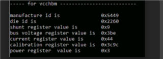
    we have got the below result from the INA226 

    Calculation like 

    Shunt voltage register: 9 * 2.5 µV = 22.5 µA  

    Bus voltage register: 0x3BE in decimal is 958: 958 * 1.25mV = 1.1975 V

    Current register: 0x44 to decimal is 68: 68 * 0.0003299865723 = 22.44 mA

    Max current and voltage of our device

    but our max current = 10.813A

    Votage = 1.2V 

    Shunt Resistor = 0.001E

    But now you can see our actual current and reading not matched so far away so can you suggest why showing this much error??

  • Bhadresh,

    This seems to be a duplicate forum thread of this one: https://e2e.ti.com/support/amplifiers-group/amplifiers/f/amplifiers-forum/1042026/ina226-ina226aidgst. I am going to mark this as resolved and consolidate over to the other thread.