This thread has been locked.

If you have a related question, please click the "Ask a related question" button in the top right corner. The newly created question will be automatically linked to this question.

OPA4388: Again with matching input impedance and total offset ....

Part Number: OPA4388
Other Parts Discussed in Thread: OPA2388, OPA388, OPA348

Hello,

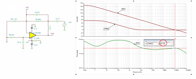
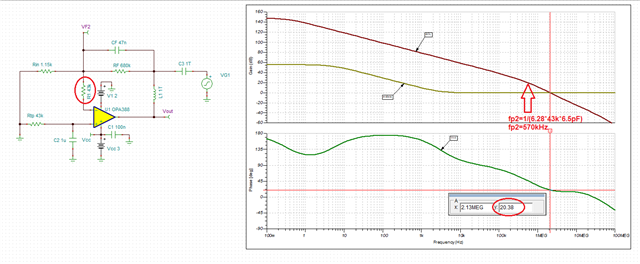
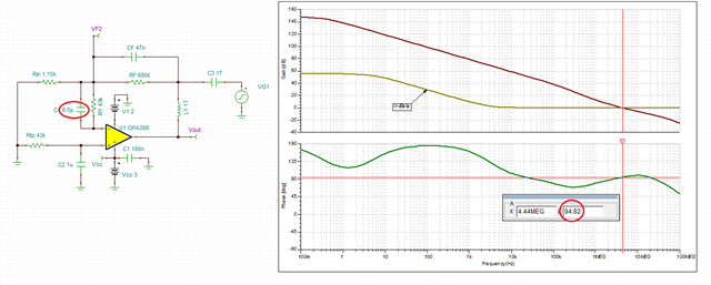
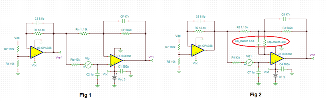
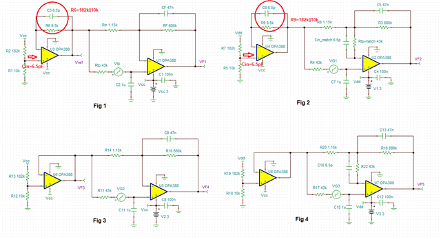
I have been suggested to use a configuration which matches the impedances at the + and - inputs, in the related previous post.

I dunno if there's something 'hidden', something I've not yet understood but using at the - input a resistor with the nearly same value the one at the + input gives a very big offset output: in the circuit below the output was nearly 0 V, having a common input of 156 mV. The sensor U15 is a thermopile, whose resistance is 43 kOhm.

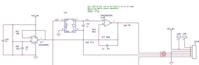
Removing R23, gives an offset values RTO of few mV but the big troubles is that it is not stable. 

at power on it is around -2.4 mV, after 15 minutes is around -11 mV and then it moves slowly between -11 and -9.5 mV.

If I use a fixed 43 kOhm resistor in the place of U15, the offset appears nearly neglectable (less the 0.25 mV) and stable (still without R23; with R23 the offset is very high again).  

I could image that the sensor U15 gets some noise, EMI and hum and they can become relevant because the gain is high, currently ~592. Or it is something related to the COMMON MODE which the internal switching "transforms" into undesirable offset.

What I ask you is a help about those offset variations: having offset is OK, it can be compensated in the subsequent processes but what I cannot compensate is its variation!

Due the very low output of the sensor, I have chosen an OPAMP with nearly no-drift in the offset with temperature..... Currently I have the OPA4388 in the prototype board, later I'll use OPA2388 or 2387... 

Any suggestion ?

Thanks

Maurizio  

  • Maurizo,

    I believe the reason for the increased offset and drift with Rtp_match resistor is that the circuit becomes unstable.

    With no Rtp_match the circuit is very stable with 101 degrees phase margin - see below.

    However, adding 43k Rtp_match interacts with OPA388 total input capacitance (Cin_diff of 2pF and Cin_diff of 4.5pF) forming a second pole at fp2 of 570kHz (see below) lowering the phase margin to 20 degrees (in simulation), which may be zero degrees in the actual circuit due to wafer process variation; minimum 45 degrees phase margin required to assure stability of the circuit over process variation.

    Adding 6.5pF cap across Rtp_match resistor stabilizes the circuit, by cancelling the second pole, and results in 95 degrees phase margin-see below.

    Therefore, since your customer calibrates the initial offset, I would suggest them NOT to use Rtp_match as shown below in Fig 1.  But if they decide to add the Rtp_match resistor they must also include 6.5pF cap across it as shown in Fig 2.

  • Thanks a lot Marek.

    I think we'll decide for NO Rtp_match but looking also at the Fig 1 & 2, I have still 2 questions:

    1. While it's clear the scope of Cin_match in Fig 2, I do not understand the meaning of C6/R9 in Fig.2 and even less C3/R6 in the Fig.1. May I have a brief explanation? In my design, U3 & U4 are OPA348: is this meaning anything? 
    2. Any guesses about the cause of the variation of the offset voltage? it's very disturbing for the accuracy of the measurements.... Rolling eyes Any way to stabilize it better?

    Thanks in advance 

    Maurizio
  • 1.  C3/R6 and C6/R9 in Fig 1 and Fig 2 were there to match the input impedance seen by the non-inverting input of front buffer.  But it should have been 9.5k (10k||182k) instead of 12.1k.  12.1k was left over from your previous (13k||182k) resistor divider you had for Vref of 200mV.  But at this point since you do not plan to use Rtp_match, you should remove it also from the buffer and use circuit in Fig 3 - see before.

    2.  Low phase margin leads to long settling time or outright oscillation that will show as voltage variation at the output. However, if you use Fig 3, the circuit is very stable with 100 degrees phase margin (see below) so there should be no issue with output moving around UNLESS NTC output is unstable and if so it’s perhaps due to ambient temperature variation.