Other Parts Discussed in Thread: UCC28180, UCC27511
Dear Ti Team,
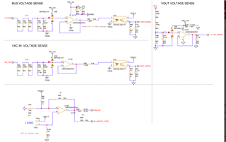
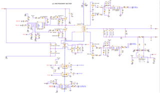
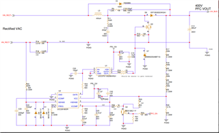
De are working on 750W charger for 2-wheeler application and we are using few Texas instruments active parts i.e. UCC27714DR, UCC27511, UCC28180, ISO7220ADRG4, INA180A4IDBVT, UCC24624DR and LM2904BQDRQ1, etc. and we have prepared the schematic and we are requesting you to verify the attached schematic before proceeding to hardware section.
Please do support us.
Note (750W charger Flow): Single phase AC mains >> Bridge rectifier >> PFC >> LLC converter >> Battery.
Labelling information in the schematic : --
1. VIN_RECT+ : Positive Rectified output terminal from bridge rectifier.
2. VIN_RECT- : Negative Rectified output terminal from bridge rectifier.
3. +VH_BUS : Positive output terminal from PFC output or Input to the LLC resonant converter.
4. BAT+ : Positive output terminal from LLC converter or charger.
5. BAT- : Negative output terminal from LLC converter or charger.
6. PWM_HIGH & PWM_LOW : PWM signals of the primary H-bridge side in LLC converter which are coming from the microcontroller.
7. SR_PWM_A & SR_PWM_B : PWM signals of the secondary Synchronous rectifier in LLC converter which are coming from the microcontroller.
8. PWM_EN , SR_PWM_EN & PFC_EN : PWM enable signals coming from the microcontroller i.e. for H-bridge of LLC, Synchronous rectifier of LLC & for PFC controller.
9. CS_LLC & CS_VOUT : Primary and secondary current sensing voltage of LLC converter respectively.
10. VIN_AC : AC rms input voltage
11. VINAC_SENSE, V_BUS_SENSE & V_OUT_SENSE : AC input voltage, output voltage sensing of PFC & LLC output voltage after signal conditioning whose are going to microcontroller.


