This thread has been locked.

If you have a related question, please click the "Ask a related question" button in the top right corner. The newly created question will be automatically linked to this question.

UCC27714: UCC27714 schematic verification

Part Number: UCC27714
Other Parts Discussed in Thread: UCC28180, UCC27511, , UCC27614, UCC27511A

Dear Ti Team,

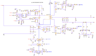
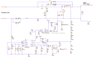
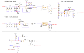
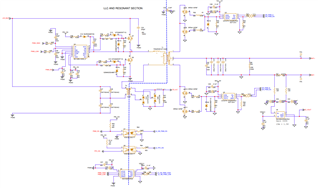
De are working on 750W charger for 2-wheeler application and we are using few Texas instruments active parts i.e. UCC27714DR, UCC27511, UCC28180, ISO7220ADRG4, INA180A4IDBVT, UCC24624DR and LM2904BQDRQ1, etc. and we have prepared the schematic and we are requesting you to verify the attached schematic before proceeding to hardware section.

Please do support us.

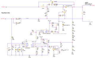
Note (750W charger Flow):  Single phase AC mains >> Bridge rectifier >> PFC >> LLC converter >> Battery.

Labelling information in the schematic : --

1. VIN_RECT+ : Positive Rectified output terminal from bridge rectifier.

2. VIN_RECT-  : Negative Rectified output terminal from bridge rectifier.

3. +VH_BUS    : Positive output terminal from PFC output or Input to the LLC resonant converter.

4. BAT+            : Positive output terminal from LLC converter or charger.

5. BAT-             : Negative output terminal from LLC converter or charger.

6. PWM_HIGH & PWM_LOW                     : PWM signals of the primary H-bridge side in LLC converter which are coming from the microcontroller.

7. SR_PWM_A & SR_PWM_B                    : PWM signals of the secondary Synchronous rectifier in LLC converter which are coming from the microcontroller.

8. PWM_EN , SR_PWM_EN & PFC_EN    : PWM enable signals coming from the microcontroller i.e. for H-bridge of LLC, Synchronous rectifier of LLC & for PFC controller.

9. CS_LLC & CS_VOUT                             : Primary and secondary current sensing voltage of LLC converter respectively.

10. VIN_AC                                                 : AC rms input voltage 

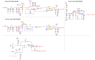
11. VINAC_SENSE, V_BUS_SENSE & V_OUT_SENSE : AC input voltage, output voltage sensing of PFC & LLC output voltage after signal conditioning whose are going to microcontroller.

Thanks & Regards,

Khageswara rao

/resized-image/__size/320x188/__key/communityserver-discussions-components-files/196/pastedimage1636458643592v3.png

/resized-image/__size/319x195/__key/communityserver-discussions-components-files/196/pastedimage1636458664312v4.png

/resized-image/__size/320x203/__key/communityserver-discussions-components-files/196/pastedimage1636458681411v5.png

  • Dear TI Team,

    please find the attached Schematics for LLC, PFC and Signal conditioning.

  • Hello Khageswara,

    Our UCC27714 expert is out today and will be back tomorrow. In the meantime, I can help a bit. I believe U4 is the UCC27714? It is labelled as MC100EL for some reason, but it appears to be the UCC27714, can you confirm that? Also, your bootstrap is 1uF and your total VDD capacitance appears to be 1.1uF. We usually recommend that the VDD capacitance be around 10x the bootstrap to prevent it from depleting when charging the bootstrap. That would be around 10uF in this case. Lastly, you may want to consider a Schottky diode from HS to ground in case the transformer's negative spikes are too much for the driver. 

    As for using the UCC27511A as a sort of DC amplifier on the controller, the implementation seems fine for that as well. You may want to consider using our new UCC27614 driver, but there is no reason why the 511A wouldn't work.

    We will try to get more experts involved for the other sections to review as well.

    thanks,

    Alex M

  • Hi Alexander,

    Thanks for your response.

    pls find the comments for your response.

    1. UCC27714               : Yes, U4 is the UCC27714 only.

    2. VDD capacitance   : Yes, we will update the VDD capacitance to 10uF.

    3. Schottky diode from HS to ground: Our nominal +VHbus voltage is 400V and could you please suggest the rating/part for the Schottky diode?

    4. UCC27614              : We are proceeding with UCC27511A.


    Thanks & Regards,

    Khageswara rao

  • Hello Khageswara,

    For the VDD capacitance and boot capacitance, we do recommend the 10X VDD capacitance value relative to the boot capacitance. I would recommend confirming if the 1uF boot capacitance value is required. Refer to the datasheet section 8.2.2.2 in selecting the boot capacitor value based on the Mosfet Qg. Oversizing the boot capacitor does not have much benefit and will result in slower high side bias charging times.

    For the diode from HS to ground, it will be a good idea to make provisions for this but may not be necessary. For 400V bus you will need a fast recovery silicon diode. Target 25-35ns recovery time if available.

    Confirm if this addresses your questions, or you can post additional questions on this thread.

    Regards,

  • Dear Richard,

    Thanks for your valuable comments.

    We are using Cboot of 0.1uFand Cvdd is of 1.1uF.

    Could please review the LLC, PFC and Sensing schematics and add if any valuable changes need to be done.

    Thanks & Regards,

    Khageswara rao

  • Hello Khageswara,

    Richard is out for the day and will take a look at this for you tomorrow.

    Regards,

    Daniel

  • Hello Daniel,

    That is great.

    Please have a Look on LLC, PFC and Sensing schematics and provide your valuable feedback.

    Thanking you.

    Regards,

    Khageswara rao

  • Hello Khageswara,

    The previous comments I provided were regarding the LLC power stage and the UCC27714. For the PFC regarding the UCC27511 driver the schematic values look OK. There is adequate VDD capacitance and I see there is provisions for a small filter on the driver input which we recommend.

    For the sensing section, I am not sure of the intended function and behavior of the various comparator circuits, but this looks like a typical implementation of various voltage sensing circuits. For detailed comments on if there are concerns on the comparators, I recommend repeating this thread with the comparator part number as the main subject line so the appropriate expert on these devices is notified.

    Regards,