This thread has been locked.

If you have a related question, please click the "Ask a related question" button in the top right corner. The newly created question will be automatically linked to this question.

OPA2192: High Side current source

Part Number: OPA2192

Hello TI TEAM

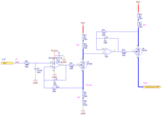
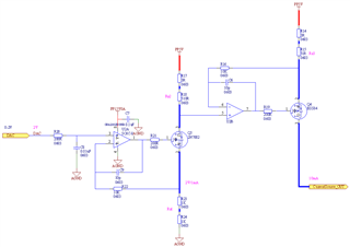
1. There is a project that is need the high side current source, I reference the thread https://e2e.ti.com/support/amplifiers-group/amplifiers/f/amplifiers-forum/1031241/tipd102-high-precision-100na-300na-current-source/3813369?tisearch=e2e-sitesearch&keymatch=Programmable%2525252525252520current%2525252525252520sources#3813369

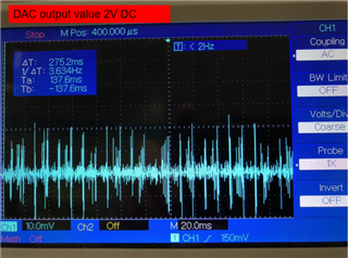
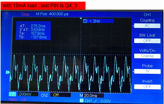
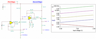
2.I found my board still had some issues. When I set the DAC out 2V DC, the second stage can achieve 10.09XmA(X is jitter bit) to driver, but the voltage that measure Q4_3 there was large ripple. Can you give some tip to resolve the phenomenon.

3. The DAC signal is from MCU DAC.

  • Hi u,

    I have hard time to read your schematic image due to the black background of the schematic. If I did not get it right, please let me know. 

    I check the stability and circuit seems to be stable with 70 degree phase margin. Please try the following. 

    The current mirror in the second stage duplicate the current source in the first stage. Please see the circled markings. 

    I changed the sensing resistor from 2kΩ to 200Ω, where the 1st stage is sourcing 10mA from the input voltage of 2Vdc. The 2nd stage is sourcing also 10mA in constant current. If the load R1  changes, VF1 will change as well due to 10mA* 500Ω.

    When the circuit is simulated from 1V<= Vin <=2V, the generated current in AM1 is in linear relationship with Vin signal. 

    BTW, Rs2=Rs3=510Ω, which is required to be the same. 

    Enclosed is the Tina simulation. Please let us know if you have additional questions. 

    current-source E2E 11162021.TSC

    Best,

    Raymond

  • Hello Raymond

    1. Thank you for your kindly reply

    I check the stability and circuit seems to be stable with 70 degree phase margin

    >> Can provide some tech doc to calculate the phase margin, I want to calculate once again。

    2.update the schematic

    Selected the NMOS is  2n7002, PMOS is BSS84, so this part number is OK for current circuit? 

  • Hi Xingmeng,

    Can provide some tech doc to calculate the phase margin, I want to calculate once again。

    You should be able to learn how to check the phase margin in the link below. We have series of video clips for different topics. The op amp loop stability consists of 7 related training videos. 

    My loop stability of the inject method is slightly different from the video clips, but the theory is identical.  

    https://training.ti.com/zh-tw/ti-precision-labs-op-amps-stability-phase-margin?context=1139747-1139745-14685-1138805-13849

    Working current source, except 2N7002 NMOS will not work. 

    The following simulation is working one per your requirements except nmos is using Si2304DDS part. 

    current-source V-to-I 11182021.TSC

    You need approx 0.5V drop across Rs2 or 510ohm resistor in order to work with the 2nd stage. So the selection of lower Rdson NMOS is critical. It is possible that I did not select a right 2N7002 model from a correct manufacture. I selected the pspice model from Diode Incorp.. 


    OPA192 NMOS 2N27002 11182021.TSC

    Selected PMOS is BSS84, so this part number is OK for current circuit? 

    BSS84 seems to be ok. Enclosed is an example of PMOS part in BW and phase margin simulation. 

    OPA192 BW Phase Margin PMOS 11182021.TSC

    If you have additional question, please let us know. 

    Best,

    Raymond