This thread has been locked.

If you have a related question, please click the "Ask a related question" button in the top right corner. The newly created question will be automatically linked to this question.

INA826: output is goes high as as soon as input is applied

Part Number: INA826
Other Parts Discussed in Thread: REF2025,

Hi,

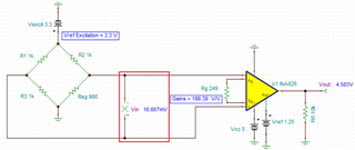
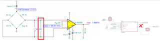
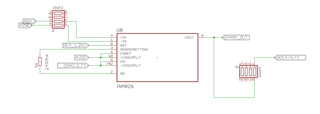
we are using a INA826 to read a strain gauge. 

here are few things

1. INA826 VCC -- 5V

2. Strain gauge is full bridge

3. Gain is set to 200 using a 249 Ohm resistance

4. Vref is 1.25V

Test case 1 -- 

No input connected -- INA826 outputs 1.25V ( as expected)

Test Case 2 --  

strain gauge connected with no strain on it. so its a balanced strain gauge and output almost no voltage. as soon as this is connected the Vout of the IN826 goes around 4V or so. 

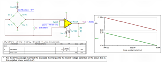
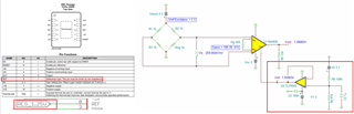
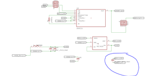
Attaching the sch of the opamp

let me know if you need anymore info

www.ti.com/.../

  • Hi Gama,

    Enclosed is your described circuit in simulation. Please check the following configurations. 

    1. If you have DRG package, please connect the thermal pad to the most negative voltage rail. If it is single supply rail, then connect the thermal pad to ground. 

    2. What is Vcm at the input?  please see the captured image below, which I believed that this is how the circuit is configured. 

    INA826 Strain Gauge 12102021.TSC

    If you have additional questions, please let me know. 

    Best,

    Raymond

  • 1. i am using single supply and its connected to ground

    2. yes my setup is identical to what you shared, only difference is that  i dont have a pull down at the Vout and Vref excitation is 3.3V. 

    I am not sure about the VCM role here. 

    the voltage between In+ and Gnd is around 1.63V and Voltage between In- and Gnd is arond 1.63V as well. 

  • Hi Gama,

    The role of Vcm is to make sure that the INA826's Vout vs. Vin (the differential inputs on top of Vcm) response are in linear relationship. Your INA826's configuration is good.

    If you are interested the tool, please download it via the link below. 

    https://www.ti.com/tool/ANALOG-ENGINEER-CALC

    strain gauge connected with no strain on it. so its a balanced strain gauge and output almost no voltage. as soon as this is connected the Vout of the IN826 goes around 4V or so. 

    Please check a couple things for me.

    a. Check the Wheatstone bridge's input's precise voltage when no stimulus is applied. In other words, make sure that the transducer is balanced.

    b. There is a chance that INA826 may be damaged for unknown reasons. It is a possibility, but I do not want to draw a conclusion currently, Currently, issue "a" is likely the explanation (the part will not be damaged easily, if it is handled properly). 

    c. Please also check the ripple voltage of your excitation voltage with a scope. Currently, I assumed that you do you have noise issues in your power rails. Please make sure that the power rails are decoupled properly. 

    If the excitation voltage for your Wheatstone bridge is 3.3Vdc, then Vin+ and Vin- should be measured 3.3V/2 = 1.65Vdc precisely. The Vout's transfer function in the circuit is Vout = Gains*(Vin+ - Vin-) + Vref, where Gains = 199.39 V/V and Vref = 1.250Vdc. 

    Let us assume the Vout is measured at 4.5V per your inquiry, then (Vin+ - Vin-) = (4.5V - Vref/) /Gains = 3.25V/199.39 = 16.3mV. Please check the differential input voltage between Vin+ and Vin- nodes, which the differential input may not be measured at 0.00mV. If the Wheatstone bridge is perfectly balanced, it should measure at 0.00mV (use higher resolution >4.5digital DMM or bench meter to check the differential input voltage) as shown in the image below. 

    Please let me know what you find. Please provide me me with additional precision voltage measurements and I will help you to troubleshoot the issues. 

    Best,

    Raymond

  • 1. Yes, the bridge is balanced. It works fine with a different strain gauge reader test meter. 

    2. The voltage between IN+ and IN- is around 0.001V.

    Let me know if you need any more info.

    Thanks

  • Hi Gamma,

    Could you check your pin assignments in INA826? INA826 should have 9 pins including the thermal pad. Your schematic is shown 10 pins. Also, the pin assignment is not matching either. 

    Please let me know why there are the discrepancy between the schematic and INA826 part. 

    Best,

    Raymond

  • i am using this package 

    www.ti.com/.../

  • Hi Gama,

    Could you show me how Reg_1.25V's circuit is implemented? If you use a reference IC, please provide me the part number. 

    The regulator for the reference pin is required to source and sink current with low impedance characteristics. The implemented circuit should look similar to an image below or use a reference voltage IC or LDO that is able to source and sink current. The Reg_1.25V reference voltage cannot come from a voltage divider, which it does not have low impedance characteristics. 

    Best,

    Raymond

  • i am using this ref ic

    https://www.ti.com/product/REF2025

    Also i just tried with gain resistor 1K and it did the same. as soon as input was applied vout went to 3.925V.

    Thanks

  • Hi Gama,

    REF2025 will be fine. 

    Please perform the following test:

    1. short the Vin+ and Vin- as is shown in the diagram below. 

    2. Remove the output connection or resistor to ADC, and measure INA826's Vout with a DMM vs. Ground. Please let me know the voltage measurement 

    Best,

    Raymond

  • Yes, i did this test earlier just o rule out any funny business form the input side

  • Hi Gama,

    Where did you measure the above scope shot from? The measured voltage is approx. 1.2x V. 

    If the differential input (Vin - Vin-) is shorted, Vout should measure approx. 1.25Vdc.  Can you show me Vout = 3.925V on the similar plot?

    Best,

    Raymond

  • when inputs are short Vout is 1.247V. as expected.

    attaching the plot when strain gauge is connected with no strain

  • Hi Gama,

    The circuit's transfer function is Vout = Gains*(Vin+ - Vin-) + Vref

    With Vout = 3.925V, the differential input calculation is going to be: (Vin+ - Vin-) = (Vout-Vref)/Gains = (3.925V - 1.25V)/199.39 V/V = 13.416mV. 

    The hand calculation indicated that there is 13.4mV delta at the INA826's differential input. You did mentioned that strain gauge is balanced and without any applied force.  Could you measure the differential input with a high resolution DMM (> 4.5 digits) anyway? I was wondering what can cause 13.4mV delta at the INA826's input under no stimulus. Do you have long input leads? Can you provide me transducer's datasheet or part number?

    Best,

    Raymond

  • 2. The voltage between IN+ and IN- is around 0.001V.

    we already measured it.

    And i also changed the gain resistor RG to 1K but the output is still 3.94V. so itf it was gain related the Vout should have changed 

  • Hi Gama,

    I am searching for clues or explanations. 

    1. Changes in Rg resistors from 249Ω to 1kΩ does not change Vout, this implies that Vout's voltage may not related to input for some unknown reasons, which it does not make much sense. Can you remove Rg resistor, where Gain = 1V/V. I assumed that you have checked that INA826 layout is correct. 

    2. I have been checking in REF2025 ref. IC. Do you have 10uF placed at the output Vbias pin (Figure 42 is shown Vref pin is used in REF2025)? Please configure Vbia pin with low ESR 10uF ceramic capacitor? (since you only use Vbias pin in the reference). 

    Best,

    Raymond

  • i changed the gain resistor just to s if vout changes. but it didn't change.

    we did check the layout. its fairly simple. 

    we do have 10uF at Vbias. attaching the sch 

  • Hi Gama,

    Ok, Vbias pin is taken care of. 

     If you remove Rg of 249Ω or 1kΩ, and Vout pin is still measured at 3.925V, then I will request to replace INA826S IC from the PCB. When Rg = Open,  Gain = 1V/V. 

    BTW, how many PCBs do you see this behavior?

    Best,

    Raymond

  • haven't tried with No RG yet.

    two PCB and both are doing this 

  • Hi Gama,

    I forgot to ask - are you purchasing INA826S instrumentation amplifiers from TI Authorized distributors? I believed that you did, but I need to make sure. 

    Please let me know what are the finding if you removed RG resistor, where Gain is configured to 1V/V. If Vout is still measured near 3.925V, the layout may have mistakes or issues etc.. 

    If you have any questions, please let us know. 

    Best,

    Raymond

  • we get all TI parts for either directly ti or Digikey.

    I think may the opamp or something in the opamp is damaged. my assumption is the baking temperature. I was looking at the solder profile and our oven was running almost 40% hotter. 

    I will reduce the temp and build a new unit i guess.

  • Hi Gama,

    Over temperature in reflow or wave soldering process may damage IC components. However, you may desolder INA826S part with a hot air gun and place a new one in place (unless the pads are damaged). 

    Please let us know what you find. 

    Best,

    Raymond