This thread has been locked.
If you have a related question, please click the "Ask a related question" button in the top right corner. The newly created question will be automatically linked to this question.
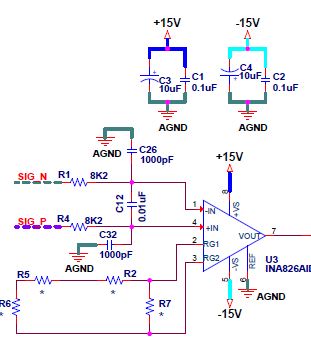
Iam using INA826 for one of the weigh bridge application. During manufacturing in few of I am facing issues like Output Voltage stauration, or output voltage gradually decreseases, or Amplifoer doesnot respond to the applied input.
Hi Tarun,
Could you share the schematic with us?
Do you mean that some of manufacturing boards have issues "like Output Voltage saturation, or output voltage gradually decreases, or Amplifier does not respond to the applied input."? Do other PCBs work properly?
This is a speculation --> Please keep the manufactured PCBs clean without soldering flux, residues, finger prints or other contamination etc.. The manufactured boards should go through ultrasonic wash cycles to remove unwanted foreign objects. Please provide us with more details, if issues are different from the speculation.
Best,
Raymond
Hi Raymond ,
Thanks for the reply.
I have assembled around 40 Pcb boards. In 40 PCB boards it found that 23 boards are working properly. In remaining 17 boards each board has different issue like gradual decrease in the output, some boards are always in the saturation etc.
I suspected the PCB Quality and Assembled AD8421 in the same place and all 17 boards are working fine. please find the attached schematic. I have assembled R2 0E, R5 220E, R6 12E, R7 open. This is calculated for the gain of 213 where my input is 12mV and output is 2.56V.
One more point is the supply provided to instrumentation amplifier is from Dual output DC-DC converter.
Hi Tarun,
can you show a schematic of the weighing bridge as well?
Have you properly filtered the DC/DC converter input and output pins? DC/DC converters are known for producing lots of annoying noise and ripple :-(
Do you have a scope plot of the supply voltages?
Kai
Hi Tarun,
The Rg of the circuit is 232 Ohm. The Gain = 1 + 49.4kohm/232 = 213.93.In order to saturate the INA826, the differential input (V+in - V-in) delta has to be above 70mV (15V/213.93 = 70.12mV).
As Kai suggested, I would take a look at the analog front end of wheatstone bridge including the excitation Vref voltage.
1. how stable is the excitation reference voltage for the weight bridge sensor.
2. What is ripple voltage on your excitation reference voltage? The differential filter cutoff frequency is approx 440Hz.
3. Assume that pin6 of INA826 is connected to stable AGND.
4. If you use AC/DC or DC/DC regulators, please filter out switching noise properly. Please use low ESR ceramic capacitors to remove high frequency switching noises at the output of voltage regulators.
Each board has different issue like gradual decrease in the output, some boards are always in the saturation etc.
Please separate the troubled boards into multiple groups, and troubleshoot one group at a time. It may be easier to approach this way. Please send us some scope shots if you are unable to figure it out.
Best,
Raymond
Hi Tarun,
Are you making progress in troubleshooting the 17 problematic INA826 PCBs? Hope the information that we provided is helpful. If you need any assistant, please let us know.
Best,
Raymond
Hi Raymond & Kai
Sorry for the late response. I am away from the work for couple of days.
1. The excitation reference voltage provided to the weigh Bridge is Stable. I have measured the ripple and attached the screen shots.
2. In my schematic the REF Pin connected to Stable Analog Ground.
3. Iam drawing my power supply from 230V to 24V using Tiny Switch and then Using DC-Dc converter for the Dual supply of 15V. I have measured the ripple of the both the supplies and attached the scope shots.
Regards
Tarun
Exicitation Scope Shots
+15V Scope Shot
-15V Scope Shots
Hi Tarun,
hhm, that's way too noisy for my taste :-(
All supply voltages must be clean, stable and noisefree! I would recommend the add of supply voltage filtering :-)
The use of switchers to generate the supply voltages might not be the best idea here, because your signal is ultra low and you must amplify ultra highly. This will only work with sophisticated and optimized low pass filtering by using Pi-filters.
Can you show the full schematic?
Kai
Hi Tarun,
I agree with Kai's comments.
Your input signals from Wheatstone bridge is only up to 12mV for nominal operation. Your excitation Vref input has voltage ripple from approx. +6mV to -11mV. +15Vdc has voltage ripple from +15mV to -12mV and -15Vdc has voltage ripple from +7mV to -12mV. These ripple noise figures are too much for the weight measurement application.
Kai has suggested some power regulator filtering method in another forum, see the link below. I think that your +/-15V power rails may need to help with such regulation. This is capacitance multiplier to filter out voltage ripple method. 2.2kOhm and 2.2uf capacitor are LPF filter and T1 and T2 are series regulators (you may also use 2N2222 or 2N3906 or other BJTs). It will do wonders to remove most of your power supply noises. If the output voltages are still noisy after the circuit is implemented, increase 2.2uf to 10uf to filter out additional noises. As it is configured, the LPF cutoff frequency is at approx. 33Hz.
The method will work well for INA826 circuit only due to low current consumption requirements. If you need to drive higher current with the circuit, then you may have to beef up the series transistor to handle to higher power dissipation.
BTW, you will need ultra low noise and stable Vref excitation voltage for the Wheatstone bridge circuit. The absolute values of +/-15Vdc or Vref are not so critical, but it has to be stable, since INA826 is only measuring the difference of Wheatstone weight sensor at its input. If you are able to fix the voltage ripple to INA826 part, most of the observed issues as you stated above should go away.
https://e2e.ti.com/support/amplifiers/f/14/p/972992/3596631#3596631
If you need additional assistant, please let us know.
Best,
Raymond
Thanks Raymond & Kai for your support.
I will Try out the power regulator filtering method & Get back to you if any additional assistance required.
Regards
Tarun
Hi Tarun,
Based on your analog front end of switching power supply, you do not have adequate filter to remove unwanted noises in the circuit. At the +/-15Vdc end, there is a pole near 1/2*pi*sqrt(10uH*100uf)=5.03kHz. So the LC filter is only attenuated the input signal after 5kHz approx., and will not attenuate low frequency noise below 5kHz. The LC rolls off at -40dB/decade and will not filter out higher noise after 40kHz or so.
In addition, there is a Q in the LC filter at 5kHz, see the plot below. Even you insert larger size electrolytic capacitors, it may not get rid of the Q as configured. By the way, WRA2415S-3WR2 is only able to source approx. 100mA (max) at +/-15mA,
As it is right now, you need to de-Que the LC output filter first and move the pole closer to <50Hz (I believe that your AC input is 220Vac @50Hz).
Here is the alternative way to do this, since you have built-up 50 units. I hate to change the design drastically at this junction.
1. Replace 10uH inductor with 100 ohm power resistor, approx. 2W. (This is based on 100mA output current). (you may stack up multiple low wattage SMD resistors to share the heat dissipation).
2. Replace 100uf capacitor to low ESR larger capacitor, 470uf if you are able to. Or parallel multiple low ESR capacitors at the output of +/-15Vdc (you can stack SMD capacitors on top of each other, if there are no spare pads). If you are able to add larger size capacitors at the output of +/-15Vdc, the LPF filter will perform even better.
3. At INA826 IC side, you need insert multiple low ESR ceramic capacitors, such as 1uf, 100nf, 1nf etc., if you are able to.
This may help the circuit to filter out most of unwanted low frequency noises.
I hope that these changes are good enough to get rid of your issues. Otherwise, you may have to improve your pi filter and reduce voltage ripple at the output of 24Vdc. Please make sure that your 10Vdc excitation reference voltage has even lower voltage ripple for the wheatstone bridge sensor.
If you are doing other improvements, you are going to alter the circuit entirely. Since there are 32 units are "working", I assumed that the performance of DC/DC converter may be adequate to meet your design requirements.
If you have additional questions, please let us know.
Best,
Raymond
Hi Raymond,
small chokes like this one, e.g.
usually provide enough series resistance to dampen the resonance of LRC-filter:
Resonance is prevented when the series resistance R > SQRT(2L/C) which is about 0.5R here.
Kai
Hi Tarun,
don't forget the Y-cap between the two signal grounds of switcher (pin 1 and pin 7)!
It's extremely important that you route two local ground planes instead of normal copper traces, one arround pin 1 and connected to pin 1 and another arround pin 7 and connected to pin 7. Let them almost touch toghether and mount your Y-cap right there into the small gap between the two local ground planes. This heavily minimizes the trace inductances of Y-cap connections. Routing conventional copper traces instead will totally ruin the effectiveness of Y-cap.
In my circuits I always put two Y-caps in parallel to furtherly reduce the negative effect of cap inductance :-)
Kai
Hi Kai,
Thanks for the damping circuit and simulation for the LRC filter.
Thanks,
Raymond
Hi Tarun,
Is the non-working circuits working with the latest recommendation?
As Kai indicated, we can damp out your LC output circuit, but you will need more components at the output of DC/DC convertor. I am trying to make the least amount of changes, since you have a product already.
Please let us know if you need further assistant. If your issues are resolved, please close the inquiry so we know that we have a good customer.
Best,
Raymond
Hi Raymond & Kai
I am Redesigning my board by implementing the LC filters & damping circuits suggested by you. For time being the Non - working boards IC's are replaced by another batch and seems to be no problem with the IC's. For Now Iam closing this issue.
Thanks for your Inputs.
Hi Tarun,
If you are going to redesign in your power supply's front end, I'd like to suggest something.
I believed that your input is 220Vrms @50Hz. From AC/DC conversion, you have a power supply. Rather than from 220Vrms to +/-24Vdc, then +/-15Vdc using DC/DC converter, you could go directly from 220Vrms to +/-15Vdc or +/-12Vdc (I know that you may have your reasons in doing your way).
Toward the end of power regulated stages, I would suggest to implement Kai's suggestion. LC filter is likely used in WRA2415S-3WR2's output stage in the DC/DC converter, which there is still 40/75mV of ripple on the regulated line. The ripple voltage is a bit high for the weight scale application.
The following circuit is equivalent to linear regulator, which it will remove most of the low frequency noises. You may increase C1 and C2 (2.2uf) capacitors and further decreasing the LPF's cutoff frequency. This filter circuit is more effective to remove low frequency noise than LC filter. To lower the poles in the LC filter, you will also need large L and C in values, nd dampen a Que with respect to the load. If you implement the any of above techniques correctly, you should get low voltage ripple and well regulated output. It is matter of component costs, part counts, PCB footprints, compact design factors etc..
Alternative, you may use LDO from 15Vdc to 12Vdc or similar, which it will provide you with good voltage regulation and low ripple noises, and it will still give you a fairly high power conversion efficiency for linear regulator (switching power regulation at front end followed by linear LDO implementation).
Please use Tina or similar simulation tools to check out power regulation, efficiency and noise ripple performance, transient performance etc.. A simulated circuit will give you better insight and reduce possible reworks down the road.
If you have any questions, you can always send us an inquiry and we will be glad to help you out.
Best,
Raymond