This thread has been locked.

If you have a related question, please click the "Ask a related question" button in the top right corner. The newly created question will be automatically linked to this question.

INA826: INA 826 unexpected Output

Part Number: INA826
Other Parts Discussed in Thread: REF3318

So I'm debugging a board that uses INA826 to amplify the output of a wheatstone bridge.

I confirmed the differential inputs to be both at about 1.6 Volts (Wheatstone bridge driven by 3.3V LDO MAX6043).

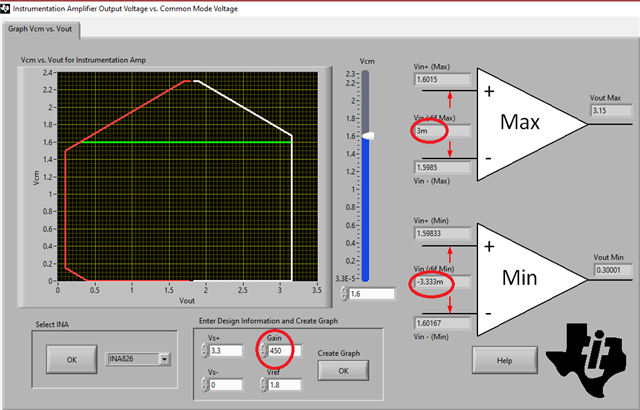
Differential Voltage is between +/- 3 mV.

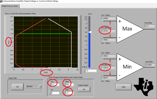
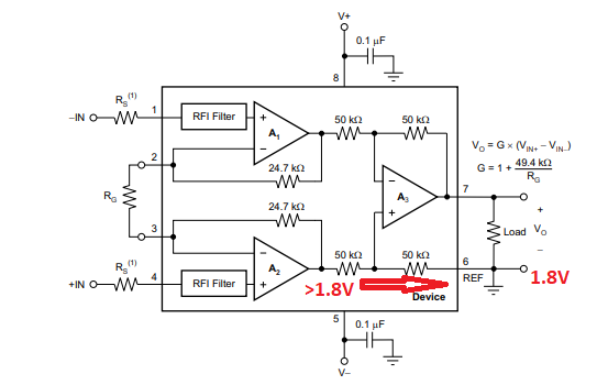
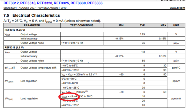
VREF is set to 1.8V and provided by NCV8114.

The positive supply of INA826 is provided by a LP38963 LDO at 3.3V.

Here you can see how the wheatstone bridge is connected to the amplifier:

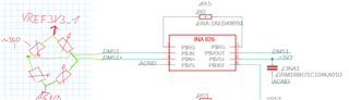
The output of the amplifier doesn't however react to changes in differential input as expected.

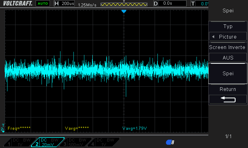
When differential input is 0, the ouput looks like this:

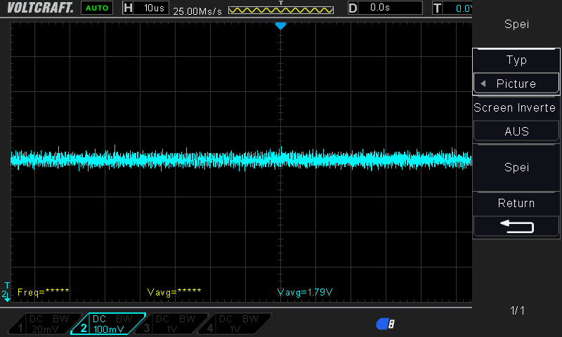
This looks okay to me, since VREF = 1.8V (see down below).

But when excitation voltage is raised to about 1mV, the output jumps to .2V.

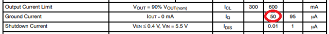
The VREF-Voltage also jumps from 1.8V to 3.3V

These are the only output voltages I can get.

Here is how I connected the NCV8114:

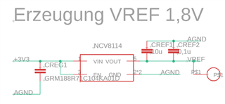
I suspect that something with my reference voltage is not okay.

  • Tobias,

    Using 49.5ohm gain resistor sets the gain of INA826 to G=1+49.4k/49.5 =~999. This means that the circuit cannot accomodate the +/-3mV input differential signals because this would require the output to go to: Vout=Vref+G*Vdiff =~1.8V+/-3V = -1.2V to 4.8V, which is not possible on 3.3V single supply.

    According to Vcm vs Vout calculator, the INA826 linear input differential voltage range under your conditions is: -1.501mV < Vdiff < 1.351mV - see below.

    If you want to maximize the input range so the Vout may reach 100mV (instead of 300mV), you must lower Vcm to 1.5V; other than that, you must lower the gain.

    You may dowload the Vcm vs Vout calculator for instrumentation amplifiers using following link: 

    https://www.ti.com/tool/INA-CMV-CALC?keyMatch=VCM%20VS%20VOUT%20CALCULATOR&tisearch=search-everything#downloads

    In order to accomodate the +/-3mV input signal, under current Vsupply, Vref, and Vcm conditions, you would have to use 110ohm Rg resistor to lower the gain to G=450 - see below.

  • Marek,

    I appreciate your reply. I understand that the maximum differential signal of 3 mV is too high for the gain of 1000.

    I will lower it to 450. Do you think that this will also improve the behaviour for small signals?

    As mentioned above, when I raise the differential input by 0.x mV nothing happens and then the ouput jumps when I reach inputs of >1mV.

    Tobias

  • Hi Tobias,

    the NCV8114 might need a minimum load current to stay in regulation. Add a 1k dummy load resistor from its output to signal ground.

    Kai

  • Hi Kai,

    good idea, thanks.

  • Hi Tobias,

    Have you checked the stability of the Vref voltage with a scope?  It is recommended to connect at least a 1uF Ceramic X5R or X7R capacitor as close as possible to the IN pin of the device. It is recommended to use ceramic capacitors for their low ESR and ESL. The recommended output capacitor value is 1uF (you use 10uF) and X7R or X5R dielectric due to its low capacitance variations over the specified temperature range. The maximum value of ESR should be less than 2ohms. It is not recommended to use tantalum capacitors on the output due to their large ESR. 

  • I connected a scope to the VREF pin. Noise is approximately 40 mVpp:

    I also tested resistors between reference voltage and ground. I used 1k and 200. This didn't change the problem.

    I wll implement the recommended capacitances in the next iteration of the board.

    Would you recommend  a specic reference voltage generator I can use? The solution of using a dummy resistor to ground doesn't sound ideal to me.

  • The fact that VREF voltage jumps from 1.8V to 3.3V tells me there is an issue with this part operating in your application.

    I believe that problem is that NCV8114 is NOT a reference voltage but rather LDO regulator (with +/-3% accuracy), which may ONLY source output current but not sink (sinking is limited to a typical quiescent current of 50uA) - see below.

    However, depending on the polarity of the input differential signal, INA826 in your application may require Vref to sink more current than ground current of NCV8114 is capable of, which will result in Vref collapsing on its positve rail - see below.

    Therefore, for Vref you should use a reference voltage like REF3318 that can sink and source output current - see below.

    Alternatively, it would be to add a load resistor at Vref pin as Kai suggested - 10kohm should be enough for the circuit to stay in regulation.

  • Hi Tobias,

    does it work now?

    Kai

  • Hi Kai,

    I've ordered a REF3318 to try it out.

  • Yes it works now, thanks!