- Ask a related questionWhat is a related question?A related question is a question created from another question. When the related question is created, it will be automatically linked to the original question.
This thread has been locked.
If you have a related question, please click the "Ask a related question" button in the top right corner. The newly created question will be automatically linked to this question.
Hi,
Customer have following issue regarding this EVM, please see details below.
"
Hi i bought your product and trying to use it and i have a question about it
I'm trying to use Fig 11 method in your user guide to use input current so i used 10M ohm to change BNC voltage input to proper current input but when i connect BNC voltage input using resistance reference output in Fig 12 is incorrrect (Only V_bias) and it is correct when i dont connect current input
My specific way to connect input is that : I use voltage input with BNC cable and connect BNC ground to High current error protection input
and connect BNC signal (voltage) to Input I1 using 10M ohm resistance and input voltage is about 100 mV
Additional Information:
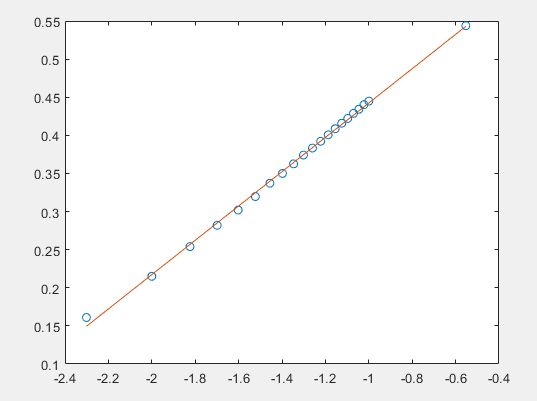
My input current's range is about 1 uA ~ 100 uA . Actually when i use 'High current error protection input' there is no change in output so i dont have data about it but when i dont use 'High current error protection input' it works and data looks like below.

Regards,
Hi Maynard,
If I interpreted the question correctly, the Customer is attempting to reproduce the setup of Figure 11, with Rtest = 100kOhm, sweeping VIN from 100mV to 10V to obtain an input current from 1µA to 100µA, to reproduce the plot /Table of results provided on Figure13 and Table1.
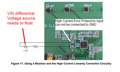
Please note that the VIN voltage source needs to be allowed to float (around VBIAS ~2V), where the High Current Error Protection Input can not be connected to GND. On the description above, the post mentions that uses a BNC cable and they connect the BNC ground to High current error protection input. Please note that this node must not be connected to GND.
See figure 11 below, VIN source floats, High Current Error protection input floats:

Please see simulation circuit and simulation result, where the data is in agreement with Table 1 of the LOG114EVM User Guide.


TINA simulation file:
Please let me know if you have additional questions.
Thank you and Kind Regards,
Luis