This thread has been locked.

If you have a related question, please click the "Ask a related question" button in the top right corner. The newly created question will be automatically linked to this question.

THS4531: ths4531

Part Number: THS4531
Other Parts Discussed in Thread: OPA344, OPA1637, OPA1632, THS4561,

Dear Sima-san,


I appreciate your many advices.


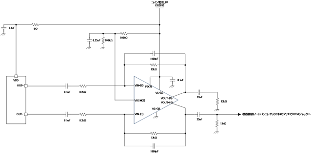
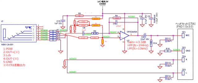
I reflected your advice (1-4) in schematic.

Is your advice correctly reflected in schematic?

If schematic is incorrect, please give specific and kind advice.


Thanks,

S.Suzuki

  • Hello Suzuki-san,

      Thank you for implementing the previous advice! It is correctly reflected in the schematic, but I have a few more pointers that I missed in the original thread. 

    1. For FDAs symmetry at the inputs/output is critical. You would also need to include the same feedback path (12kOhm, 1000pF) from pin 8 (VIN+) to pin 5 (VIN-), and remove 12kOhm at the input of VIN+. 
    2. I would still consider using a transformer at the output of the amplifier if distortion is an important specification in your design. If not, it is designed correctly this way as well. 
    3. Attached below are the Gerber files for the THS4531EVM which might help efficiently design a high speed PCB using the THS4531.

       The values look standard enough, but I will run a stability simulation. I will update this thread by end of the week.

    6528462C.zip

    Thank you,

    Sima

  • Hello Suzuki-san,

      Attached below are the simulations with AC response of the above schematic and of a multiple-feedback filter version. Frequency response shows a bandpass filter (approx 1kHz to 15kHz), and stability sims shows circuit stability with 80 degrees of phase margin. 

    8015.THS4531.tsc

    THS4531_MFB.TSC

    THS4531_Stability.TSC

    Thank you,

    Sima 

  • Dear Sima-san,


    Thank you reply.


    > 1.

    > For FDAs symmetry at the inputs/output is critical. You would also need to include the same feedback path (12kOhm, > 1000pF) from pin 8 (VIN+) to pin 5 (VIN-), and remove 12kOhm at the input of VIN+.

    I am very interested in this comment.


    Q1.

    I reflected your advice (1) in schematic.

    Is your advice correctly reflected in schematic?

    If schematic is incorrect, please give specific and kind advice.


    Q2.

    Can THS4531 be expected to operate normally if your advice (1) is not applied?

    In other words, I want to know if your advice (1) is mandatory and must be addressed.


    Thanks,

    S.Suzuki

  • Dear Sima-san,


    Thank you reply.


    I couldn't browse * .tsc file.

    If possible, I expect to even share in formats such as PDF format.


    Thanks,

    S.Suzuki

  • Hello Suzuki-san,

    1. Yes, the schematic is now correct. I do not see anything else that needs to be modified
    2. Yes, this feedback network on both sides are mandatory for fully differential amplifiers (FDA) to work. Unlike a standard difference amplifier, both feedbacks are needed to stabilize the device and symmetry between two paths is critical for CMRR performance. This app report on fully differential amplifiers goes into detail on the reason found on page 4, figure 2. Below is a simplified version of Figure 2 which shows that you can think of this as "two amplifiers" integrated and Vocm error amplifier depends on both inputs. 
    3. Yes, I can share them as images instead. If you would like to modify the simulations, please download our free simulation tool, Tina-TI, which can be found at this link
      1. Schematic AC Sim

      1. MFB Butterworth Filter AC Sim

      1. Stability Sim 

    Thank you,
    Sima 

  • Dear Sima-san,


    Thank you reply.

    I want a final confirmation.


    Q3.

    Is THS4531 the best mic amp to meet my needs (differential input, single output)?


    Q4.

    I am trying to manufacture a board with the following circuit using OPA344.

    Can this circuit be expected to work properly?

    Thanks,

    S.Suzuki

  • Hi Suzuki,

    are Ra and Rb mounted?

    What are the output signals of the source at the left?

    What is the purpose of the 32R resistor?

    Kai

  • Hello Suzuki-san,

      Q3. What are your input characteristics (frequency, Vpp)? Is this for an audio application, if so I would also look into OPA1637 and OPA1632. I would also look in using THS4531A (has better DC specs compared to THS4531) and the THS4561. 

      Q4. Unfortunately, I can not help here since this product falls under general purpose amplifier portfolio. Would you be able to create a new thread/post with this same question plus answers to Kai's questions?

    Thank you,

    Sima 

  • Dear Kai-san,


    Thank you reply.


    > are Ra and Rb mounted?

    Not implemented.


    > What are the output signals of the source at the left?

    It's a microphone.

    It is a special note that this microphone has a differential output.


    > What is the purpose of the 32R resistor?

    Earphone equivalent load.


    Thanks,

    S.Suzuki

  • Dear Sima-san,


    Thank you reply.


    >  Q3. What are your input characteristics (frequency, Vpp)? Is this for an audio application, if so I would also look into OPA1637 and OPA1632. I would also look in using THS4531A (has better DC specs compared to THS4531) and the THS4561.

    Input characteristics is accelerometer microphone.

    I think that answer to your question is given on pages 11 and 13.

    invensense.tdk.com/.../Sonion-Voice-Pick-Up-VPU-Sensor-Paul-Clemens.pdf


    >  Q4. Unfortunately, I can not help here since this product falls under general purpose amplifier portfolio. Would you be able to create a new thread/post with this same question plus answers to Kai's questions?

    I answered Kai-san's question.


    Thanks,

    S.Suzuki

  • Hello Suzuki-san,

       Thank you for sharing the documentation. It looks like the accelerometer at 1kHz gives a sensitivity of around 50mV/g. With a measured noise density of 3.4µg/√Hz, you would need a noise voltage density of around 0.17µV/√Hz or 170nV/√Hz. And, if you look at equivalent input noise bar graph which gives an average of -95dBg, this also translates to around the same voltage density. Therefore, the THS4531A will be able to distinguish between the sensitives with a Vn of 10nV/√Hz at 1kHz. You could also use THS4561 at 4nV/√Hz or OPA1637/OPA1632 at 1nV/√Hz. Any of these devices would work for your application, but THS4531A will give you the lowest quiescent current which is most likely most beneficial for your design. 

       Thanks for answering Kai's question on the OPA344. On my end, I do not see any complications/concerns with the schematic. But, would double check with the general purpose amplifier team. The signals to the input of the amplifier might be violating the input common-mode range specification of the device. Would you be able to ask the same question using this link: https://e2e.ti.com/search?q=&category=forum ? Please make sure to include the device name OPA344, so the thread will be routed to the correct team.

    Thank you,

    Sima 

  • Dear Sima-san,


    Thank you reply.


    Q3.

    I recognize that THS4531 series has two part numbers, THS4531 and THS4531A.

    You recommend THS4531A out of THS4531 and THS4531A.

    Is my understanding correct?


    Q4.

    I have responded to your request.

    Please check it.

    e2e.ti.com/.../opa344-opa344


    Thanks,

    S.Suzuki

  • Hi Shinya,

    would this be the circuit?

    shinya_OPA344.TSC

    And this be the datasheet of microphone?

    ics-40619-datasheet.pdf

    Kai

  • Hello Suzuki-san,

      Q3. That is correct, I would recommend the THS4531A because of the improved DC specifications over the THS4531. 

      Q4. Thanks! Looks like the team issued similar concerns and included fixes/suggestions. 

      Thanks Kai on creating the simulation circuit file.

    Thank you,

    SIma

  • Dear SIma-san,


    Thank you reply.


    I thank you for your response.

    I will try to manufacture a board with THS4531A.


    Thanks,

    S.Suzuki