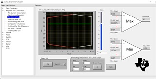
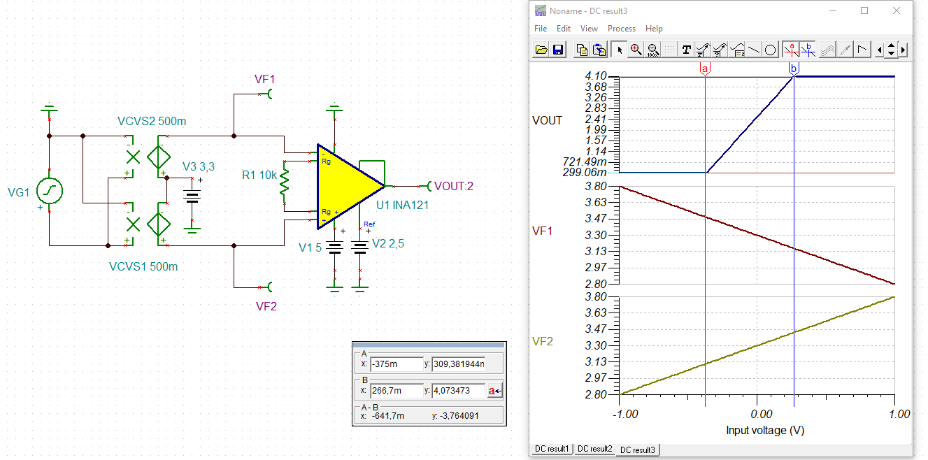
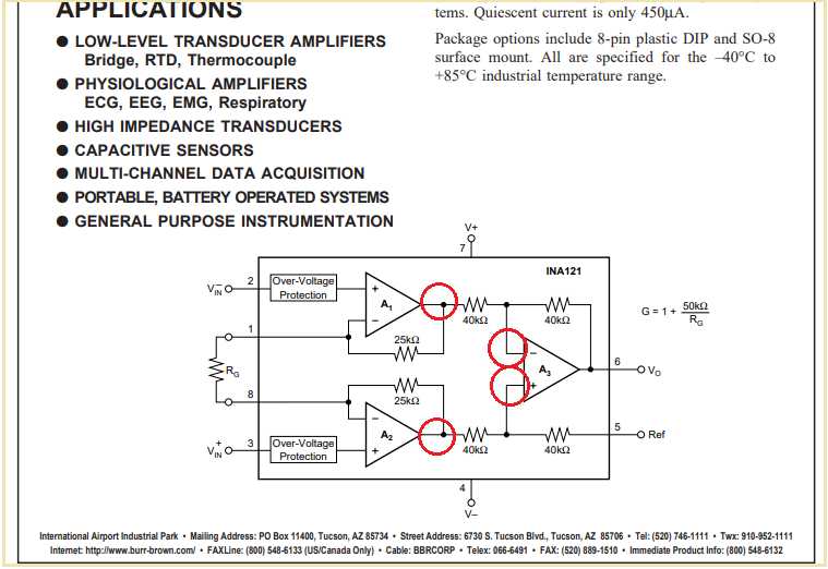
I've been using the Analog Engineers Calculator to determine areas of operation (VCM vs VOUT) for the two instrumentation amplifiers listed in the thread title. I have succeeded in building an amplifier from each of the two INA's on prototype boards with a single 5V source, along with the a 2.5V reference voltage and a 3.3V VCM. They work as advertised.
My question concerns interpretation of the data shown at the right side of the app window, which shows the Min and Max Vout and associated input data. It is the latter that I have been unable to interpret, although I understand that the numbers in question result from the solutions of equations. In particular, I do not have a picture of what is meant by the terms: Vin (dif MAX) and Vin (dif MIN), in particular what they tell me about the operating range and how I can use them to predict what will happen in the associated circuit.
I'm attaching a jpeg which shows a typical screen for the INA 121 circuit I'm working with. Any light you could shed on interpreting these values would be greatly appreciated.
Thanks,

Not sure about the image size here, but the input parameters are: INA 121, V+ 5V, V- 0V, VRef 2.5V. Gain 6, VCM 3.3V
Bob Edwards


