Hi
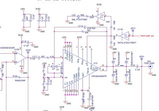
I'm using below circuitry on my custom card. But the circuit is failing continuously. I don't know why it is happening.
I'm enabling output only with 10% duty cycle at a repetition rate of 1Hz.
The load is a capacitive load of value (139.1, -57.48) (imepdance magnitude, phase angle degrees) at 51KHz & (565.4,-34 .23) at 63KHz output signal.
1. Is there any layout guidelines to be followed.
2. Is the input protection diode (BAT120S,115) selected proper.
3. What happens when EN pin toggles at PRF 1Hz , will it affect OPA564.
Please clarify.