This thread has been locked.

If you have a related question, please click the "Ask a related question" button in the top right corner. The newly created question will be automatically linked to this question.

THS4551: THS4551

Part Number: THS4551
Other Parts Discussed in Thread: ADS127L11, TINA-TI, THS4531, THS4531A

Hello,

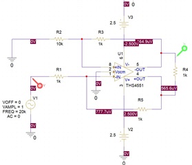
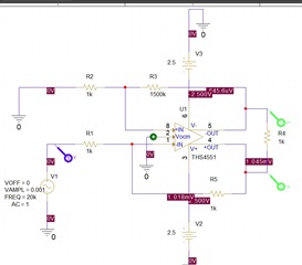
I'm a new user, and  I would like to use a AOP THS4551. After download PSpice for TI, I can draw the electronic assembly (see in this attached the picture) but when I'm trying to simulate, It's impossible. Do you know what is stopping me from doing the simulation ?

Thank you for your helps.

Regards   
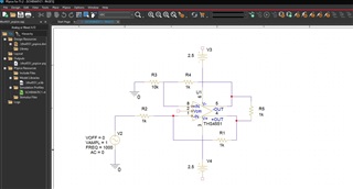
     

  • Hhm, the ground symbol is missing at V3 and V4.

    Kai

  • Hi Kai,

    Thank you now I have something but I need to know the variation of the output voltage as a function of the input voltage.

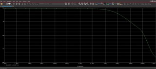
    But I have only this curve : 


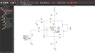
    Probably I didn't choose the right parameter (see the red circled)? 

  • Hello,

    Next to the red area you selected in your screenshot, you can see the simulation profile 'Schematic1 - ac sweep'.  You'll want to switch to a time domain profile or create a new simulation profile.  An AC frequency analysis will not provide voltage output as a function of voltage input.

    When you create a simulation profile, you can choose what type of analysis to perform.  I am guessing you want to do a transient analysis as the input voltage varies over time; you can then plot the output voltage with a voltage probe.  For 1000Hz sine wave, I recommend a time domain simulation run-time of 1ms.  After you run the simulation, you can edit the X-axis variable (by double-clicking on the x-axis) to be the input voltage (V1) rather than Time, and now you can view a plot of the output voltage as a function of the input voltage.

    You can use a second probe on the other side of R4 to see how the FDA output behaves according to the input.

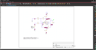
    Please see the following images and let me know if you were intending to accomplish something else:

    THS4551_E2E.zip

    Best,

    Alec

  • Hi Alec,

    Thank you for your helps, I'm a new user you say : 

    'You'll want to switch to a time domain profile or create a new simulation profile.'

    Yes but I have only one choice 'SCHEMATIC-ac_sweep' in my scrow bar, probably when I create a new simulation profile I must choose in time domain. I will see how to do it, if you have any information how to do it i am interested 

    My goal is to know the max gain, because I've a very small signal comes from a hydrophone about : 0.1µV and 1.78 mV. So I wonder if I need 2 AOPs instead of just one ?

    After downloading your version, I've just I changed some settings. I run the simulation and something is wrong, the gain of my amp is 1 but the output voltage is lower than input voltage. Please see in this attached.   

    Thank

    Regards

    Yann           

  • Hello Yann,

    Thank you for sharing more about your application.  Could you elaborate on your input source and amplifier needs? 

    • If your input is a hydrophone, will the input source to the amplifier be differential?  In our circuits above, the input is single-ended.  
    • What is the frequency of the input signal?  You have been modelling 1kHz; the THS4551 is a high speed (150MHz) FDA; depending on your needs you may prefer a precision FDA or other op-amp.
    • Hydrophone inputs are small signals; what gain would you need to operate the FDA in to enable your application?

    Regarding capacitive sensors, please examine the following links for ideas and resources:

    https://e2e.ti.com/support/amplifiers-group/amplifiers/f/amplifiers-forum/196000/amplifier-for-hydrophone-use-of-giga-ohm-resistor-in-circuit

    https://e2e.ti.com/support/amplifiers-group/amplifiers/f/amplifiers-forum/355929/hydrophone-amplifier/1249975

    https://e2e.ti.com/support/amplifiers-group/amplifiers/f/amplifiers-forum/785496/hydrophone-fully-differential-amplifier-differential-input-differential-output

    https://e2e.ti.com/support/audio-group/audio/f/audio-forum/136962/high-impedance-piezo-hydrophone-amplification---general-hints

    The following two TI articles discuss working with piezoelectric sensors:

    https://www.ti.com/lit/an/slyt369/slyt369.pdf

    https://www.ti.com/lit/an/sloa033a/sloa033a.pdf

    For the signal you are observing in your simulation:

    • Why is did you select R2 to be 10K?  When considering FDAs in a gain of 1V/V, you should have Rf & Rg be equal, such that Av = Rf/Rg
    • This article discusses data acquisition and proper calculation of R values for sensor/gain needs: https://www.tij.co.jp/jp/lit/an/slyt119/slyt119.pdf
    • I made a mistake when sending you the file earlier; please see the attached screenshot which shows the use of the differential probe.  Using the correct measurement method will properly display your expected 1V/V gain.

    Best,

    Alec

  • Hi Alec,

    Thank you for your helps with a lot of information...But I have already chosen the Hydrophone and Preamp now I just need to amplify the signal : from 0.1 µV to 1.77 mV for a frequency between 10 Hz and 20 kHz. I chose this Amplifier because I have already chosen an ADC and this ADC recommends using this amplifier, it's for reason that I would like to simulate the input signal of this amplifier. 

    I wonder if it is possible to enter such a low amplitude signal (µV) via a signal generator ? So I'll test the circuit after your remark about gain.

    Thank

    Regards

    Yann DO 

  • Hi Alec,

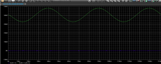
    In fact with the generator I can simulate a 1 mV voltage :

    And after I can have Vs=f(Ve) with my specification but I don't know why I have a negative output offset about -6mV.

    Probably, it's not very important because I am in differential mode ? 

    Thank

    Regards.

    Yann DO    

  • Hello Yann,

    I am glad you were able to generate a 1mV voltage.  For your offset issue, you should keep R3 & R5 equal; I am not sure why you increased R3 to 1500kOhm but left R5 = 1kOhm.  When I match the resistor values to set them equal to each other, I observe expected output without the large offset.

    Once you decide on your gain, make sure to match the feedback resistors R3 & R5.  If you do not do this, the FDA will demonstrate an output offset like you observed in your attached image.  Because of the structure of FDAs, there are issues that will happen when feedback resistors are not matched, including output offset issues.

    Best,

    Alec

  • Hi Alec,

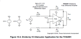
    According to the assembly of the circuit in the datasheet below : 


    It's normal that I vary the resistance to seek the maximum gain (without distortion). But it's not the same resistor normally we do it with R5 (RF1) and R1 (RG1) and not with R3 and R2 like your answer earlier. And the second point is the output voltage of AOP is inverted with respect to the input signal. Because we're in an inverting amplifier. 

    After reflection, it was necessary to invert the probe at the output to have the right signal. 

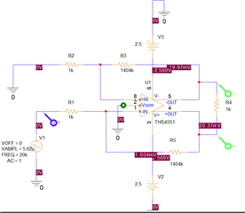
    I was able to simulate with a 5.62µV input signal (which corresponds to my low level of the hydrophone) see this picture below : 


    I can see a little offset about 40mV,  probably I must use a capacitor to remove the offset ? What's do you think about this solution ?

    Thank for your helps.

    Regards.

    Yann DO


  • Hello Yann,

    I am glad you are able to simulate the small input voltage.  I am going to look at some methods for accounting for your observed offset.  Where are you considering adding a capacitor in the circuit?  As you discovered, the THS4551 datasheet does discuss several use cases and implementations, including driving ADCs.

    Please read these two Planet Analog articles, which will help you address the causes for the offset: 

    https://www.planetanalog.com/signal-chain-basics-148-understanding-the-impact-of-offsets-in-fully-differential-amplifier-circuits/#

    https://www.planetanalog.com/dc-precision-considerations-for-high-speed-current-feedback-and-fully-differential-amplifiers-insight-4/

    I have also attached a TI document on FDA offset voltage and the contributing factors which enable DC offset.

    https://www.ti.com/lit/an/slva417/slva417.pdf

    Best,

    Alec

  • Hello Alec, 

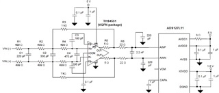
    I read the first link and the last link that you gave me, apparently it's not that simple! Yes I use this AOP (THS4551) with a ADC (ADS127L11), this is my purpose to amplify the signal coming from the Hydrophone. 

    After DS (DataSheet) on page 73.

    I need to amplifie the signal in differential mode and I'm not sure if my AOP in inverter is in differential mode. Give me some time to read all the information you gave me but I'm not sure to find the solution to eliminate the 40mV offset. 

    Thank you for your patient.

    Regards

    Yann DO

  • Hi Alec,

    After going through all the information about AOP THS4551, I don't see the solution to compensate for the 40mV offset. I can also see :

    'This output CM offset is usually of negligible concern in driving ADCs that show some tolerance on their input common mode voltage range (when specified) far exceeding these <+/-20mV output Vocm errors.'

    So probably if I connect directly to ADC 'ADS127L11' the signal will be better ? Sorry but I have no solution how to compensate this offset for my ADC. 

    Thank you for your helps.

    Regards.

    Yann DO

  • Hello Yann,

    I am taking a look at some options today for your design. 

    I will update you once I confer with my team for next steps or best implementation for to account for the observed offset.

    If you have a more complete/full circuit you can share (with the ADC perhaps), I would appreciate the extra information.  If you are mainly simulating and designing the FDA portion, I can investigate typical circuitry for your application.

    Best,

    Alec

  • If you have a more complete/full circuit you can share (with the ADC perhaps), I would appreciate the extra information.  If you are mainly simulating and designing the FDA portion, I can investigate typical circuitry for your application.

    Hello Alec, 

    Thank you for your helps, yes my goal being to use this FDA (AOP THS4551) with the ADC (ADS127L11) because I am going to order these materials and I would like them to correspond to our specifications. I have meetings and trips, I'll come back to you next week with the new elements (I will do my best).

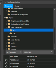
    I just looked at the ADC library and apparently we don't have the ADS127L11 component in the library to do the simulation.  Which I think there is no choice but to work only with AOP-THS4551.


    Regards,

    Yann DO

  • Hello Yann,

    I am working on simulating some ideas for your circuit.  While I am doing this, you may use TINA-TI to simulate a system with both the THS4551 & the ADS127L11.

    I will follow up with more questions and any updates I have.

    Best,

    Alec

  • Hello Yann,

    I have some follow-up points:

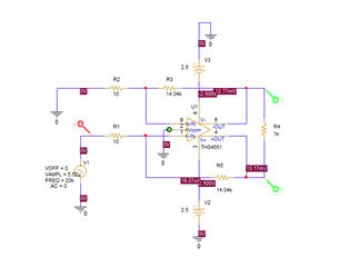
    1. What is the output impedance of the hydrophone sensor?  Could you operate the circuit with 10 Ohm gain resistors and 14.04 kOhm feedback resistors?  If your sensor is okay with a low input impedance at the FDA, you would only have a 25mV offset instead of 40mV.  Please provide details regarding the sensor you are using and its impedance profile.  See the following images:

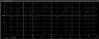
    Fig1: Vout across load resistor w/ 25mV offset

    Fig2: Schematic w/ smaller resistor values

    2. This behavior shown above (the difference of 15mV of offset) is due to the input bias current offset caused by large resistors.  As stated in the Planet Analog articles I linked in a prior answer, the output offset due to bias current is strongly affected by large resistors, such as the 1404kOhm (~1.4 MOhm) feedback resistor.  

    3.  Earlier you mentioned adding capacitors to the circuit; I was unsure what you intended to accomplish with these capacitors.  Were you thinking of AC-coupling the ouput of the FDA?  If you only need the AC signal and do not require the DC signal, this would be a good choice to minimize the DC offset voltage you are experiencing.  The issue will be choosing the right value capacitor, as you are operating at low frequencies correct?

    4. Finally, you may prefer to use the THS4531 or THS4531A, which is very similar in performance to the THS4551, but has a much lower maximum bandwidth.  As you are operating in a low-frequency range, this choice might benefit your design cost.

    Best,

    Alec