This thread has been locked.

If you have a related question, please click the "Ask a related question" button in the top right corner. The newly created question will be automatically linked to this question.

LMV324: Follower with saturation problem.

Part Number: LMV324

Hi, 

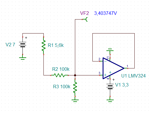
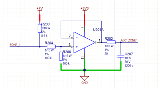
I have a design of an Op. Amp. in a follower configuration, made it for use in the previous stage of an ADC input. The circuit, is the following

The circuit was tested on another desing using the IC LMV324AIDR, and it work great. 

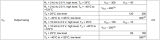
On a new manufacture, the LMV324AIDR was out of stock, so I made the decision to replace it with the LMV324IDR (I check out all the datasheet, and I didn't notice any big difference) . When the boards arrive, I tested the circuit, and I notice that the output of the LMV324IDR have a saturation on a high level in 2.69 V aprox. (The Op. Amp. Supply it's 3.3V). Is these behaviour correct? I check the datasheet again and didn't find any information related to these issue.


BR,

Mauro


  • Hey Mauro, 

    Here is the difference document between the LMV and LMVA families: https://www.ti.com/lit/an/sboa368/sboa368.pdf

    Can you please explain "LMV324IDR have a saturation on a high level in 2.69 V aprox." Does this mean that the output stays at 2.69V constantly? What did the LMVA op amp output (what is the expected output)? 

    I built your circuit in simulation and didnt immediately find any red flags. Could you please provide what the value of "Zone_1" is? I tested a 100mV sine wave with a DC offset of 1.65. 

    All the best,
    Carolina

  • Hey Mauro,

    It's also worth adding that the circuit as configured in the schematic violates the common mode voltage range of the device. 7 volts on that input divide divides down to 3.4V (outside your supply rails of either device).

    Additionally the LMV324A can drive a larger capacitive load than it's non-a counterpart. Both datasheets go up to 1000pF with the A version above 20 degrees of phase margin, and the non-a version below 20 degrees PM. These are devices with different architectures (A is CMOS and non-A is bipolar), so they will have different output impedances. You may need to increase the size of your isolation resistor for stable operation.

    Also, your output voltage swing from rail varies largely between these two devices.

    Non-A version at 2.7V

    Non-A version at 5V

    A version Device

    Best,
    Jerry

  • Whether this was a good idea to give two totally different OPAmps the names "LMV324" and "LMV324A" only to be distinguished by the "A"?

    Mauro,

    as my previous speakers have already mentioned, as long as nothing is connected to "zone_1" the common mode input voltage range of LMV324 is heavily violated:

    mauro_lmv324.TSC

    The datasheet of LMV324 says that the common mode input voltage must stay 1V below the supply voltage.

    Kai

  • Hello Mauro, 

    Was the issue resolved? I will go ahead and mark Kai & Jerry's response as "TI Thinks Resolved". 

    If the issue wasn't resolved, please let us know so we may further assist. 

    All the best,
    Carolina