This thread has been locked.

If you have a related question, please click the "Ask a related question" button in the top right corner. The newly created question will be automatically linked to this question.

INA2181: Crosstalk between two motor current sensing

Part Number: INA2181
Other Parts Discussed in Thread: INA2180-2181EVM, , INA240

•Two motors are drove alternately with their currents monitored by INA2181A1IDGSR (R=50mΩ, Imax=2A) .

•Crosstalk of IN2 --> IN1 is big, while no crosstalk of IN1 --> IN2.(IN1 is connected to Motor1 and IN2 to Motor2)

•Crosstalk is roughly proportionate to PWM frequency.


•Is there any good way to reduced the crosstalk ? 

  • Hello Masaki,

    Is the voltage on the input changing?  Is the current sensing on the PWM side?  What is the voltage change on motor 1 vs motor 2?  You could have large voltage spikes causing the issue.  Can you share your layout?

  • Is the voltage on the input changing?  Is the current sensing on the PWM side?  What is the voltage change on motor 1 vs motor 2?  You could have large voltage spikes causing the issue.  Can you share your layout?

    Yes, I can share oscilloscope measurements, circuit diagram and layout. Please check them.

    Oscilloscope observation 220325.ppt

    Hapkit for Robotics Hub v23.pdf

    Hapkit for Robotics Hub_2022-02-12.zip

  • Hello Masaki,

    The problem does not seem to come from the other channel as the output of ChA does not correspond with the output of CHB or the input PWM of CHB.  None of the signal match up.  Could the GP27/ADC1/I2C1_SCL  be driving that pin from the RASPI_PICO?  To test this you could easily remove R204 and look at the output.  Or look at the configuration of the GP27 pin of the RASPI_PICO.  The reason I lean toward this being the issue is there is no correlation with the inputs/outputs of the other channel to the output change of the CHB.  Also the output is changing form positive to negative rail somewhat like what a SCL signal would do.

  • Thanks for comments.

     Could the GP27/ADC1/I2C1_SCL  be driving that pin from the RASPI_PICO? 

    My first oscilloscope pictures are so extreme case that they are misleading.

    So I have prepared another observations, where I come to notice that the problems occurs only when sensing register are near to +5V.

    When potential of sensing resister is near +0V, I noticed that there are no crosstalk between two channels.

    Could you please check the following ppt ?


     Oscilloscope observation 220326.ppt

  • Hello Masaki,

    I will keep looking at attempt to reproduce on a INA2180-2181EVM.  I will need a couple days to get in the lab.

  • Thanks for your attempt.

    I noticed one thing. If you can comment on this, I'll appreciate it.

  • Masaki-san,

    I will help answer your question here while Javier is working in the lab.

    The reference voltage won't be the saturation point as per your question. The reference voltage is passed to the output of the amplifier as a Vsense = 0V condition. For each individual amplifier inside the INA2181, they should be able to reach up to Vs-.03V in the worst case. This is where the amplifier will saturate:

    Since your REF is set at 1.8V in your example and Vs is 3.3V, this gives you 3.27V-1.8V =  1.47V of referred to output resolution in the forward direction, and 1.795V in the reverse direction (swinging to GND). 

    So, the condition of saturation in the forward direction would actually be

    RSENSE*Im*GAIN > 1.47V

    If this condition is reached, then yes, the output will, saturate. This will not damage the amplifier, but the output obviously will no longer be accurate, and it may require time for the output to return to linear operation when the saturation condition is corrected.

  • Masaki,

    I did not see anything at the output when manipulating the input of Ch2 and observing Ch1.  Can you look at the VS pin and Vref pins to see if there are any issues with the driving of those pins.  Also can you check the GND of the device vs the input.  As you are switching is the GND and PGND changing that it causes issues with Input being below GND?

    I cannot see where else this could be coming from.

  • Thanks for your experiment. 

    I again checked Vs, Vref, GND, PGND in the experiment.

    What do you say to this ?

  • Masaki,

    You have me stumped.  I am thinking to see what else it could be?  Like I said I experimented with the EVM and applied both transient VCM and transient Vsense voltages and I did not see much cross talk at all.

  • Masaki,

    I had a co-worker look at this and he mentioned you could have damaged the device by having the input common mode go below the Absolute Maximum Ratings.

    Can you add some protection and try a new device?

  • Can you add some protection and try a new device?

    Thanks for your comment.  I'll try.

    Is the protection something like this, which will cut the spikes.

  • Hi Masaki,

    I think your circuit is a victim of inductive kickback of motor:

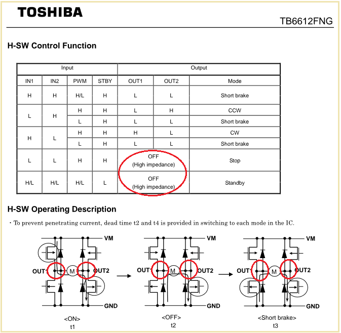
    I think the case where the output is directly switched from the "run" mode into the "stop" mode with both outputs being "off" is critical. Maybe you can avoid this situation by first "short braking" the motor before going into "stop" mode?

    But of course, there's still a risk that inductive kickback takes place during normal "run" mode. One would have to perform some oscilloscope measurements to be clear what's going on.

    Figure 55 and 56 show some protection circuits using TVS to protect the inputs of INA2181 against too high common mode input voltages. But unfortunately they do not protect the inputs against negative going input voltages. And even when installing additional diode clamps or even Schottky diode clamps the inputs of INA2181 might not be fully protected to -0.3V because of eventual inductive kickback in the motor wiring. Another disadvantage of such a protection scheme is that the common mode rejection can dramatically degrade due to the imbalance introduced by the additional TVS, diodes or Schottky diodes.

    I would carry out through oscilloscope measurements to see what kind of inductive kickbacks the circuit has to withstand. Then, I would look for a suited current sense amplifier which can easily handle the observed under- and overvoltages. I guess this will be an amplifier which can handle negative common mode input voltages way below -0.3V.

    You can also try to swap the outputs of motor driver, the inputs of current sense amplifier and the location of shunt. But I think this will only marginally improve the situation.

    Kai

  • Great thanks for additional information on motor driver usage.

    Yes, I have been using "stop" mode. So I soon changed the software to use "run-short breaking" PWM.

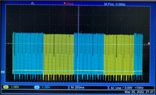
    The picture is the voltage on both ends of sensing register. There seems to be inductive kickbacks.

    My question is:

    * Is CR filter effective to cut spikes below -0.3 V ?

    * Does CR filter improve amplifier accuracy in general when input includes higher frequency > 350 kHz ?

    * If so, is it a good idea to merge Figure 48 and Figure 55 for better performance ?

    Masaki Yamamoto 

  • Hi Masaki,

    the filter you have shown is a differential filter only filtering differential input voltages, or by other words voltages between the two inputs. But these are not the problem here. The issue is the common mode input voltages of both inputs, or by other words the voltages from each input to signal ground. These voltages mainly contain the destroying inductive kickbacks and these would need filtering. So you would need to add filtering caps from each input to signal ground.

    The problem is, as I already wrote above, that such a common mode filtering can dramatically degrade the common mode rejection due to the imbalance introduced by the manufacturing tolerances and drifts of filtering capacitors. That's the reason why common mode filtering is not recommended in the datasheet. It would do more harm than good.

    Why is a huge common mode rejection necessary?

    Both inputs see large input voltages which only differ by the very small voltage drop across the shunt resistor. The INA2181 shall only amplify the small voltage drop across the shunt, but not the nearly identical voltages of both inputs. These large common mode input voltages shall be suppressed as much as possible. But when you introduce an imbalance at the both inputs the INA2181 can longer do this because in the two input low pass filters common mode input voltage is unwantedly transformed into differential input voltage. This can totally ruin the awesome common mode rejection of INA2181. As consequence you will see a huge portion of the common mode input voltages at the output of INA2181 which can no longer be suppressed.

    Also, I think that the time constant of an usual low pass filtering is not sufficient to fully filter out inductive kickback. One would need to zoom into the scope plots of inductive kickback to see what low pass filtering time constant would be needed.

    So, maybe I'm wrong, but I think that your inductive kickbacks of about -1V...-2V cannot be simply handled by the INA2181 by merely adding some low pass filtering and diode clamps. But let's wait what the TI's experts are saying to all this.

    Kai

  • Another thing to look as is use one of our devices that reject the common mode transition from a PWM signal.  The INA240 and the new INA241 that is in preview mode.

  • Thanks for comments, Kai and Javier.

    • I have replaced the old INA2181 device into a new one.
    • I have also modified the controller software so that motors won’t be disconnected from power source.
    • Catastrophic crosstalk disappears, but small signal remains which is proportionate to PWM frequency.(Red line is INA2181 out2 which is monitoring motor current, blue line is out1 which is monitoring zero current)

    I’m going to challenge a new circuit with common mode CR filters, even though Kai has pointed out that it might do more harm than good.

    I’ll also be waiting for the new INA241 device coming to the market.

  • Hi Masaki,

    besides taking a better suited current sense amplifier there are several other remedies:

    1. You could mount additional kick-back Schottky diodes in parallel to the internal MOSFET body diodes as shown here:

    http://wesleythoneycutt.com/tb6612fng-motor-control-board-update/

    The major disadvantage of this measure is that the junction capacitance of these kick-back diodes must not be too big. Otherwise you short circuit the MOSFETs for a brief period everytime when the MOSFETs turn on.

    2. Another approach is to shift the power ground of motor driver relative to the signal ground of current sense amplifier so that the common mode input voltage range of current sense amplifier is no longer violated. The disadvantage of this method is that all the control signals at the inputs of motor driver had to be shifted as well.

    3. The simplest remedy of all is to put the shunt not into the motor lines but into the supply voltage line "VM1,2,3" of the motor driver. Of course, in this case you would need to take an individual motor driver for each motor.

    Kai

  • Masaki,

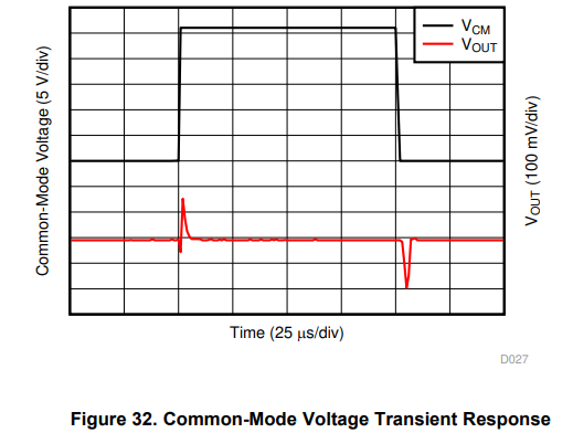
    Javier is out of office today so I can chime in here. I agree with Kai's assessment, especially #3. Whenever any of our devices is exposed to a rapid change in common mode at the inputs, it will exhibit a response to it, as we show in our datasheets. Here is the INA2181:

    Some of our devices, such as the INA240 and the INA241B Javier has mentioned, are designed with this in mind, and contain algorithms that help mitigate this error, but all of them will have some amount of response when the common mode changes. 

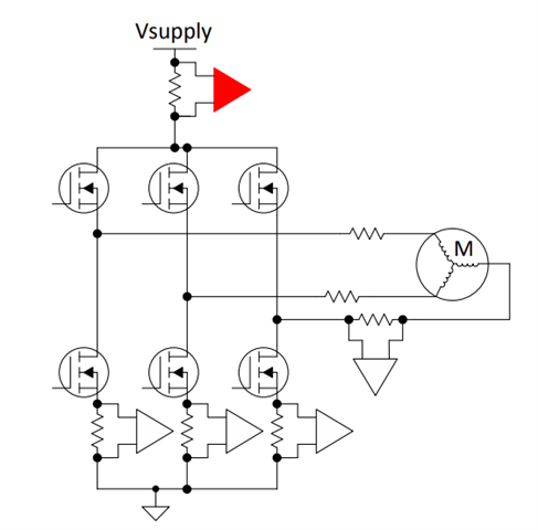
    If the error you're seeing in the INA2181 is too great for the application, you can move the amplifiers to the high side or the low side, as shown here. Note that this image shows the high side as an average measurement, where the low side shows discrete amps for each motor as Kai mentioned. The amplifier in the middle is your current measurement attempt, which we refer to as in-line:

    Measuring at these points in the circuit remove the common mode pulsing from the measurement, as the shunt now sits at a constant roughly Vsupply. Is this something you are able to do in your circuit?

  • Thanks Kai,

    3. The simplest remedy of all is to put the shunt not into the motor lines but into the supply voltage line "VM1,2,3" of the motor driver. Of course, in this case you would need to take an individual motor driver for each motor.

    Thanks Carolus,

    I agree with Kai's assessment, especially #3.

    I'm tempted to go for it, but can it measure the short braking currents like this ?

  • Hello Masaki,

    If you place it on the high side it will not be able to measure the current for t2 or t3.  If you can I would suggest moving to the INA240 or the INA241 if possible.  

  • Hi Masaki,

    this leads to the rhetorical question: Why do you measure the motor current at all?

    Kai

  • Thanks Javier,

    If you can I would suggest moving to the INA240 or the INA241 if possible.

    I'll definitely wait for them.

  • Thanks kai for comments.

    Why do you measure the motor current at all?

    I want to measure current to experiment on disturbance observer, where by knowing current precisely I can estimate disturbance and correct it to get better position control performance.  

    The reason why I need two current from two motors is for bilateral control experiment, where position and torque of one motor is exactly mirrored to the other and vice versa. 

    If I were using brushless DC motor, I could have used current measuring circuits shown in Carolus two days ago. But in my case, I'm using DC brushed motor for simplicity and leading to this problem.

    Masaki Yamamoto

  • Hello Masaki,

    I would recommend you order samples of the INA241A or INA241B.  They are available now and they have the PWM rejection.  We have some other devices that are similar and have the same pin out but do not have the PWM rejection INA296A and INA296B.  You can also order and EVM of these devices seen on the product page to experiment with.

  • Hi Javier,

    I would recommend you order samples of the INA241A or INA241B.

    Are you saying samples from TI ? 

    I can not find any in Digikey.

  • Hello Masaki,

    Yes.  You will have to order from TI.  Click on link and scroll down and order.  You will need to order them through the website.