This thread has been locked.

If you have a related question, please click the "Ask a related question" button in the top right corner. The newly created question will be automatically linked to this question.

VCA2615: Amplifiers forum

Part Number: VCA2615

Hello mr. Chen Kung.

Excuse me for the late reply, I had no possible to do it.

I did not understand your answers.

>Please refer to the VCA2615 datasheet Figure 61 page 19,
>Let's assume you are using active feedback termination,
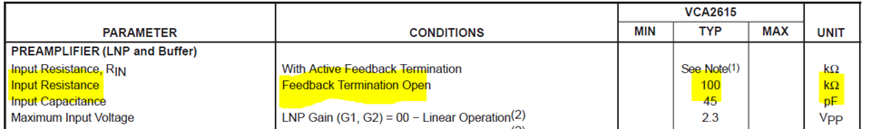
Yes, active termination.
But firstly I worked with the code = '1111', so active termination = 100 KOm.
And I got output noise voltage
Uout,rms=1.2mV

> this shows LNP Gain as 20dB (vs. your setting is ~16dB)
As I thought there was real LNP Gain = 22dB (according Table2)
I worked with single ended input, so Gain was = 22-6=16dB.

>also it shows 8 different kinds of LNP Noise levels,
I did not find in the text an explanation of where these 8 curves of Noise Figure came from and what they correspond to.

>you can see the curve (it shows Noise Figure vs. source Impedance = Feedback Resistor values)
>which is very similar to your test Curve results as well (showing in mV).

Lets take curve corresponded to 1nV/√Hz
In second stage of experiment I set for the code = '1110'
it corresponded to Rfb=1500 OHm, so
Rin,active = 206 OHm
and I got
Unoise,out,rms=2.14mV
(Rs=0 or Rs=50, amplifier gain = 52dB)

Where you looked here results similar to datasheet Figure 61 page 19 ?

Also I do not understand discrepancy between Figure21 and Figure61.
Figure21 shows NF=2dB (smallest value) for Rs=0.
But Figure61 shows maximum value of NF for Rs = 50 OHm.

Can you explain what is my mistake ?

Thank you,

Best regards,
Viktor.

  • Hi Viktor,

    Apologies for delayed response. 

    I am supporting the VCA device and I would really appreciated if you could share the background information or thread behind the same?

    I am not able to follow the above conversation with Mr. Chen Kung. 

    Can you share previous details you had with Kung?

    Thanks & regards,
    Abhishek

  • Hi Abrishek

    Thank you for your reply.

    Below this text you will find initial post and the answer from  Mr. Chen Kung.

    Regards,

     Viktor.

    =======================================================

    Hi all

    I use VCA2615 in ultrasonic application.
    On the page 18 of Data Sheet
    Table 5. shows codes for Feedback Resistor Settings.

    I have come across that setting any code other than
    '1111' (Open) causes a significant increase in noise.

    For example, for code = '1111', input termination Rl=0, amplifier gain = 52dB
    (about 16dB for LNA with a single ended input plus 36dB for VCA)
    output noise voltage
    Uout,rms=1.2mV

    For code = '0000'
    Uout,rms=3.59mV
    For code = '0001'
    Uout,rms=3.57mV
    ..................
    For code = '1101'
    Uout,rms=2.44mV
    For code = '1110'
    Uout,rms=2.14mV


    Please answer two questions:
    1) Why is this happening?
    2) What is FEEDBACK RESISTOR for code '1111' (Open) ?

    Thank you,

    Best regards,
    Viktor.


    Hi,

    for your questions:
    1) Why is this happening?

    Please refer to the VCA2615 datasheet Figure 61 page 19,
    Let's assume you are using active feedback termination,
    this shows LNP Gain as 20dB (vs. your setting is ~16dB)
    also it shows 8 different kinds of LNP Noise levels,
    you can see the curve (it shows Noise Figure vs. source Impedance = Feedback Resistor values)
    which is very similar to your test Curve results as well (showing in mV).

    2) What is FEEDBACK RESISTOR for code '1111' (Open) ?
    Please also refer to the datasheet page 17,
    it mentions in the open position, the input resistance of the LNP is about 100kohm.
    Thank you!

  • Hi Viktor,

    Thanks for sharing the details. I understood the problem.

    So, when you set FB1-4 as '1111', essentially meaning open; the input resistance (Rin) will be 100 kohm as shown in the datasheet.


    Also, note that the Rin is the input resistance and with active termination, Rin is a function of feedback resistor and LNP Gain. 

    So, for say LNP gain of 18 dB:

    Rin (0000) - 26.15 ohm

    Rin(0001) - 28.77 ohm

    Rin (1110) - 301 ohm and so on.

    So, as you see in general, when source impedance is increasing (only talking about active termination case) the noise figure is decreasing from the plots, your data also suggests the same.

    As it is a very old device, I am also not much familiar, hence, about the 8 different noise levels, let me go through the datasheet in more detail and align with the design team. I will provide you the correct and precise explanation.

    In the meanwhile, i would suggest you to download the simulation files from the product page and play around with that, it may give you an answer you are looking for. In parallel, I will also do the same and share you my findings.

    Kindly allow me some time.

    Thanks & regards,

    Abhishek

  • Hi Abhishek
    Thank you for the quick reply.

    1)
    >So, for say LNP gain of 18 dB:
    >Rin (0000) - 26.15 ohm
    >Rin(0001) - 28.77 ohm
    >Rin (1110) - 301 ohm and so on.

    As I think it is not entirely accurate.

    LNP gain = 22 dB (according Table 2. Gain Selection of LNP)
    22db ~ A=12.59 - for differential input (and half as much - for single ended input)

    So,
    Rin (0000) = Rf/(1+(A/2))=130/(1+(12.59/2))=17.9 Ohm (equation 5 on page 18)
    Rin (0001) = 19.6 Ohm
    ........................
    Rin (1110) = 205.6 Ohm

    >when source impedance is increasing (only talking about active termination case) the noise figure is decreasing from the plots, your data also suggests the same.
    yes, of course.
    But
    for Rin=205.6 Ohm Uout,noise,rms=2.14mV
    for Rin=100 KOhm Uout,noise,rms=1.2mV (that is much less !)
    I did not find any mention of this noise behavior in the Data Sheet for this amplifier.

    So any active impedance matching for
    FB4,FB3,FB2,FB1=0000...1110
    always give more noise than for
    FB4,FB3,FB2,FB1=1111 (Rin=100 KOhm).

    Why then do we need active resistance matching?
    After all, the chapter "ACTIVE FEEDBACK TERMINATION" talks about active termination as a way to reduce the amount of noise.
    But as I think it is impossible to get less noise than for
    FB4,FB3,FB2,FB1=1111 (Rin=100 KOhm).

    2)
    where from 8 curves (Figure 61, Figure 62) of Noise Figure came from and what they correspond to ?

    3)
    Also I do not understand discrepancy between Figure21 and Figure61.
    Figure21 shows NF=2dB (smallest value) for Rs=0.
    But Figure61 shows MAXIMUM value of NF for small value of the Rs.
    Could you please explain it?

    Many thanks.

    Best regards,
    Viktor.

  • Hi Victor,

    Apologies that I missed this message. I had replied quite a while back and seems like somehow my reply didn't went through earlier.

    I calculated the Rin for 18dB (similar to yours at 22dB). That's all.

    For an amplifier say non inverting, you have noise figure (F) = 1 + NA/NI; where NA is the amplifier noise and NI is the contribution due to source and the termination. The noise figure is just noise factor in logarithmic scale.

    So for an amplifier where you are giving input to the positive terminal with source impedance Rs, termination resistance Rt, you will have 

    NI = 4kTRs  x (Rt/(Rt+Rs))^2 

    If you have Rt - infinity i.e open then you will have NI = 4kTRs

    when Rt = Rs then NI = kTRs

    Hence, without termination you will find the lower noise figure. But the signal integrity will be compromised and you will see very poor system performance.

    It goes to the transmission line fundamentals, if you don't match the impedance, you see a lot of reflections which in turn will degrade performance.

    So, this answers the need of termination.

    The active termination provides lower noise performance as compared to conventional termination. This is discussed in detail in the datasheet.

    So, you are correct that it is impossible to get less noise than for
    FB4,FB3,FB2,FB1=1111 (Rin=100 KOhm).

    2) The 8 curves are just shown for comparison between the active termination and standard termination case especially highlighting that active termination is better in terms of achieving lower noise. The 8 curves just represent the different LNP noise as representation numbers, for eg if LNP noise is 0.6 nV/rtHz, how does the NF varies with source impedance. They are not device numbers, just representational numbers that's all. The actual device data is provided in the specification table.

    3) Figure 21 shows the variation of NF with Vctrl and it has smallest value at max gain as shown, but with Rs = 0; Figure 61 does not show any value at Rs = 0. The LNA Gain is 2 dB different and VGA noise also may be different.

    Thanks & regards,

    Abhishek