This thread has been locked.

If you have a related question, please click the "Ask a related question" button in the top right corner. The newly created question will be automatically linked to this question.

LM2904: Please help tell the difference between different 15TI and 22C5 datecode LM2904DG

Part Number: LM2904

Dear Expert

from the measurement, we can confirm this issue was related to the TI chip, we need TI to investigate the difference between different 15TI and 22C5

Below is the measurement result of different D/C by DMM.  we can found that the input(pin3) of U19 is almost same, but the output is different(pin1) of U19.

U19

15 TI

22 C5

V(Pin1-GND)

0.46629V

0.43086V

V(Pin3-GND)

0.36785V

0.36873V

V(Pin5-GND)

0.27284V

0.25796

V(Pin6-GND)

0.27775V

0.25682V

V(Pin7-GND)

3.7671V

3.5264V

Pass/Fail?

Pass

Fail


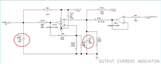
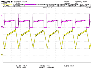
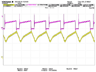
Measure the signal by oscillator, can found the outputpin1 of U19 is different.


Mark :22 C5

Mark :15 TI

CH3: pink U19-pin3


Ch1:Yellow U19-pin1

  • Hello Gabriel,

    Was the voltage table measured with a fixed DC input? The differences are slew rate and the strength of the always on sink driver. Because the load is restive and capacitive, the output current may be greater or lesser than the 'always on' sink driver. Therefore the high power output transistors of the op amp are sinking in the left picture and sourcing in the right picture. This is a natural result of the LM2904 output stage and the application load. As a test, try adding a 1k ohm or less resistor from pin 1 to ground. If I am correct, then 22C5 will now look more like 15TI (22C5 main output transistor will now be sourcing)

    See sections 3.1 and 4.3

    Design Guidelines for Devices with LM324/LM358 Cores

  • Hi Ron

    Yes, the voltage table measured with a fixed DC input, if The differences are slew rate and the strength of the always on sink driver,  then what’s the tolerance ? why we didn’t observe this issue in the past for >10millions ? please check.

  • Hi Gabriel,

    do not directly touch any pin of OPAmp with the DMM or scope but insert an isolation resistor of >100R first.

    Also, you heavily dynamically overload the LM2904. The 310kHz input signal contains extremely far reaching harmonics and by this you run the LM2904 way beyond its possibilities. You should either low pass filter the input signal and/or take a much faster OPAmp.

    Kai

  • Gabriel,

    The table doesn't make sense for DC input. The output should be same as the input unless the output was at it's maximum current. There are two DC loads on the output, 10.5k and 909k. The 10.5k requires 43uA of current from the op amp.  What is the voltage on the other side of the 909k? To get the numbers shown below, it would need to be over 60V (to make op amp sink enough current)

    U19

    15 TI

    22 C5

    V(Pin1-GND)

    0.46629V

    0.43086V

    V(Pin3-GND)

    0.36785V

    0.36873V