A related question is a question created from another question. When the related question is created, it will be automatically linked to the original question.
If you have a related question, please click the "Ask a related question" button in the top right corner. The newly created question will be automatically linked to this question.
The XTR117, XTR116 and XTR115 belong to a family of 2-wire current transmitters intended for 4-20mA current loop applications. In a 2-wire current transmitter application, the current transmitter is powered by the 4-20mA current loop, where the two analog wire loop carries both the power for the sensor/transmitter and the 4-20mA sensor signal. These 2-wire transmitters are commonly used to monitor a remote sensor when there is no access to a local supply.
Since the transmitter (and sensor) consumes a certain amount of quiescent current, a 2-wire current transmitter can not be used on a 0-20mA current output application, because the output will not be able to reach 0mA at the zero-scale input level, since the transmitter circuitry consumes current.
The following blog explains this concept in great detail:
A 3-wire transmitter can be used with a local supply to transmit a 0mA-20mA, 4-20mA (or 5mA to 25mA) current signal. On a 3-wire transmitter, one wire is connected to the local supply of the transmitter. A second wire connects the shared ground of the transmitter and receiver. The third wire carries the analog output signal
The XTR111 is a 3-wire current transmitter that can be used on a 0mA-20mA current output application. The XTR300 and XTR305 can also be configured as 3-wire current transmitters.
Please check the links below, which cover important concepts of current loop transmitters, and explain the differences between 2-wire and 3-wire current transmitters in detail.
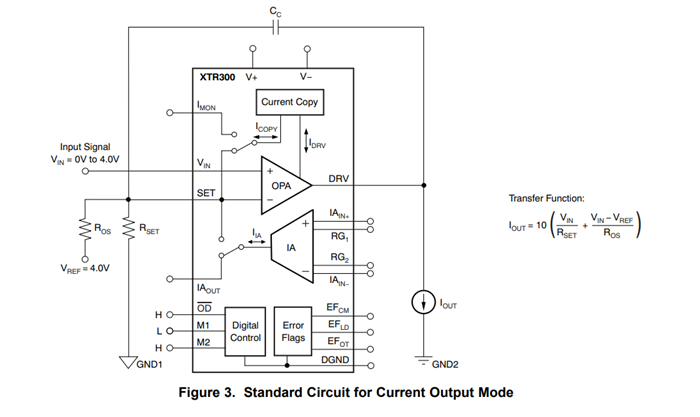
of course can the XTR300 source and sink current at the output. Why not looking at figures 3 and 42 of datasheet? With Rset = Ros = 2k the output of XTR300 can source 20mA and sink -20mA.
You mean that it can work as 2-wire and 3-wire current transmitter, as explained by Luis?
As the frontpage of datasheet of XTR300 clearly says, the XTR300 can only work as 3-wire current transmitter.
It's impossibe for a 2-wire current transmitter to work from 0mA to 20mA, because the electronic circuitry of current transmitter always consumes some supply current (<4mA).
Please carefully work through the links given by Luis.
The XTR111, XTR300 and XTR305 are 3-wire current transmitters, they need to be powered with an external supply outside the current loop.
As I have explained above, these devices can not be used on a 2-wire current transmitter application.
The XTR111 is a 3-wire transmitter that can only source output current.
The XTR300 and XTR305 can either source or sink current, or provide a positive/negative output as documented both on the XTR300 and XTR305 datasheet or TIPD155:
The standard circuit for current output mode on figure 3 of the datasheet shows the transfer function for the XTR300 and XTR305, where the current output is a function of the input voltage.
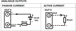
But my requirement is Active /Passive loop configuration for 0-20mA output.
Pls find below image for Active/passive loop for 0-20mA current output and also find the reference module link for better understanding. The attached module generates both 0-20mA & 4-20mA with Active/Passive loops. As per my understanding i'm thinking this is the 2-wire configuration.
Can you please verify once, as per this ref module can we generate 0-20mA in both Active/Passive configuration with TI XTR devices.
many manufacturers have their own spellings when it comes to "2-wire" and "3-wire" sensors. This is not helpful because this results in lots of confusion. I would recommend to stay with the "2-wire" and "3-wire" spelling.
The words "2-wire" and "3-wire" only make sense when you think of a "naked" sensor outputting a signal current to a receiver. "Naked" means that it does not have an own supply voltage but needs a supply voltage from the receiver.
Then, "3-wire" means that the sensor outputs a signal current over two lines, the signal line and the ground return line and that it needs an additional supply voltage coming over a third line. The ground return line of the signal line is also used as the ground return line for the supply voltage. By this methode signal currents down to 0mA can be generated.
"2-wire" means that the sensor gets a supply voltage over one line and outputs the signal current over a second line. There's no ground return current. The ground reference is only formed in the receiver. Because of that only two wires are used. But because the current transmitter in the sensor needs some supply current and supply voltage to work, only signal currents of more than 4mA can be generated. Even if the current transmitter circuitry would need less than 4mA, then the current transmitter always forces a current of 4mA to flow. This is accomplished by using a very clever method where the input circuitry of current transmitter floats relative to the loop power supply and the ground reference of the receiver.
it's very unusual that a sensor provides two outputs, a "3-wire" and "2-wire". A usual sensor is either "2-wire", if it is loop powered (by a supply voltage provided from the receiver) or it is "3-wire", if the sensor needs an additional supply voltage with an additional ground return current path.
It's the job ot the receiver to allow both kinds of sensors to be connected. So the receiver must allow "2-wire" and "3-wire" but the sensor is only "2-wire" or "3-wire".
So what exactly are your needs?
Must you build a "naked sensor" outputting a signal current? Or must you build a "circuit" outputting a signal current?
Next question: Must the "naked sensor" or the "circuit" get power from the receiver?
Next question: Must you be able to output "0...20mA" and "4...20mA" because the receiver is not able to switch between these two ranges? Or what else is the reason why you must output both ranges?
Next question: Must you be able to output "0...20mA" and "4...20mA" because the receiver is not able to switch between these two ranges? Or what else is the reason why you must output both ranges?
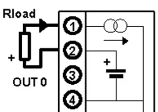
No. i'm able to generate 0-20mA only. but i want to generate in this configuration
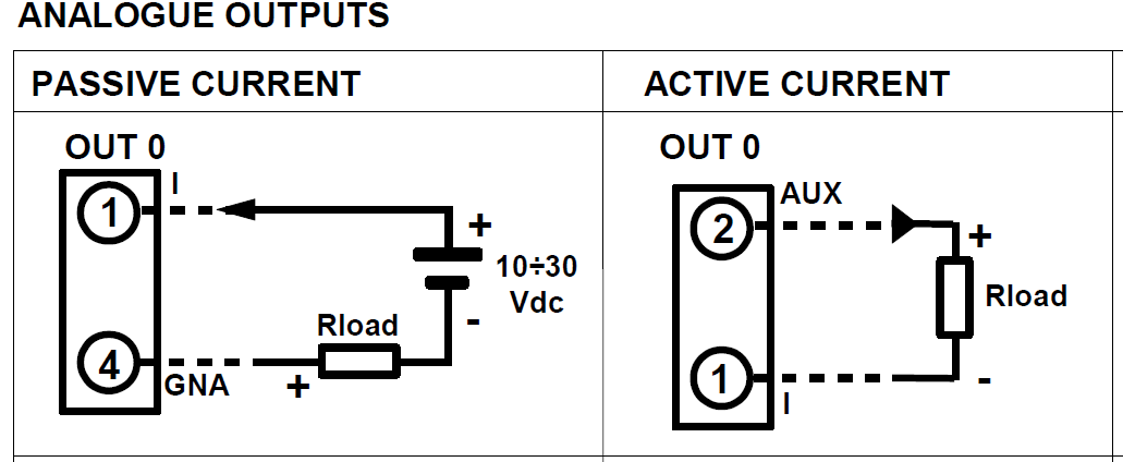
so you want to make your circuit work with receivers which only have two terminals and which either have "I" and "GNA" terminals or "AUX" and "I" terminals? Or by other words, a receiver which supports "passive current" does not support "active current" and vice versa?
In this case both methods are incompatible and you cannot switch from the one method to the other by simple jumpers.
If the "passive current" method would provide a third terminal for the ground return current (Rload-), you could drive it like the "active current" method.
The XTR117 (2-wire current transmitter) will not work on the 0-20mA current output application.
The XTR117 current transmitter and sensor circuitry consumes an amount of quiescent current; therefore, the 2-wire transmitter will not be able to reach 0mA at the zero-scale input level. On a 2-wire current transmitter application, the minimum zero-scale scale needs to be set above the overall transmitter circuit current consumption. This includes the current consumption of the XTR117, sensor, and any circuitry connected to the current loop. The quiescent current consumption of the XTR117 stand-alone can be as high as 200µA, plus you will need to account for additional current consumed by the sensor or current transmitter circuitry.
Currently, there is no XTR117 TINA or XTR117 PSPICE model. The XTR117 was released to market about 17-years ago, and no model was released with the product at the time. A simplified XTR117 TINA simulation file has been shared by engineers on E2E forums. This TINA file emulates the idealized current output transfer function of the XTR117. The TINA file circuit is built using ideal components, and it is helpful as a tool to verify the XTR115/6/7 RIN resistor selection, to check the overall current output transfer function when using the device on the recommended 2-wire 4-20mA application. Keep in mind, this XTR117 simplified simulation does not model the XTR117 quiescent current consumption, offset, AC frequency response, supply headroom limitations or dynamic behavior of the XTR117. The simulation is not a replacement for the device datasheet, application notes, tutorials or documentation that has been provided above.
Your “passive” configuration above is only compatible with the XTR117 (2-wire) on a 4mA - 20mA output application, but as I have explained, it will not work on a 0mA to 20mA application.
The XTR111 could be used on the “passive current” configuration if a third wire connection was available to connect to the GND of the XTR transmitter to the Rload (-) connection, making it a 3-wire configuration. For Clarification (7-19-22), the XTR300/XTR305 are 3-wire current transmitters, but please keep in mind, the XTR300 and XTR305 also require to be powered by bipolar+/- supplies, and therefore will not work in the "passive current" configuration without the additional Rload(-) to XTR ground connection, and without an additional negative -VEE supply.)
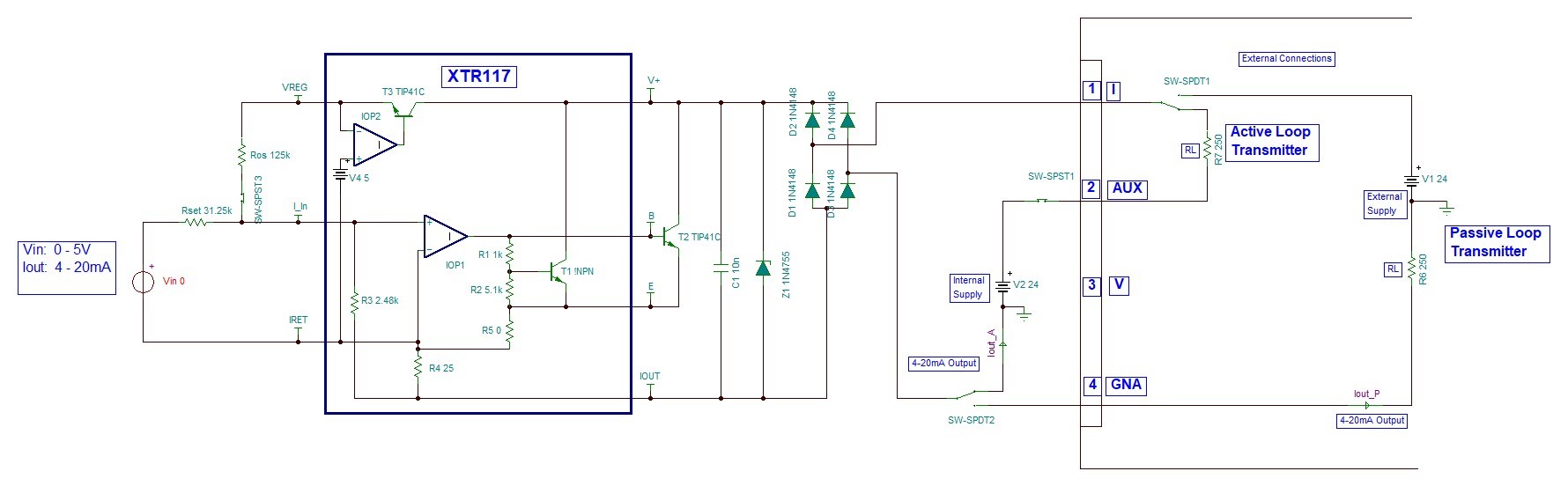
Ok sir... I understood... i shared the tina file of XTR117. In this i simulated the both Active & Passive configuration for 4-20mA output... Can you please verify once.. Is this design is ok for 4-20mA output in both active & passive configuration...
Next question: Must you be able to output "0...20mA" and "4...20mA" because the receiver is not able to switch between these two ranges? Or what else is the reason why you must output both ranges?
I'm asking for verifying the Active & Passive configuration... That's why i simulated and shared the XTR117 design to do verification of concept is working or not.
Present, based on all your suggestions and references i am going with 3-wire transmitter for generating 0-20mA output in both active & passive modes...
So, now i am sharing the simulation and results files to verify the circuit function....Please go through once is this circuit will work or not
And One more thing Presently XTR110KP (Through hole) Part number is available in stock but SMD part (XTR110KU) is not available...
And also 3-wire XTR family devices are not available in stock. Can you please provide the stock information or can you please suggest stock available part number for 3-wire current transmitter..
Regarding the XTR117 (2-wire) question on the previous post, the XTR117 will work on the ‘passive’ 4-20mA configuration as you show above while powered with a loop +24V supply. Since this is a 2-wire transmitter, it will also be able to sink the 4-20mA as you shown on your ‘active' configuration.
Please ensure, the total current consumption, that is the current consumption of the sensor/circuit producing the VIN 0-5Vsignal plus the quiescent current consumption of the XTR117 (~200µA), is less than 4mA. As you have shown in the TINA simulation, the circuit/sensor generating the input voltage needs to be referred to the local IRET potential.
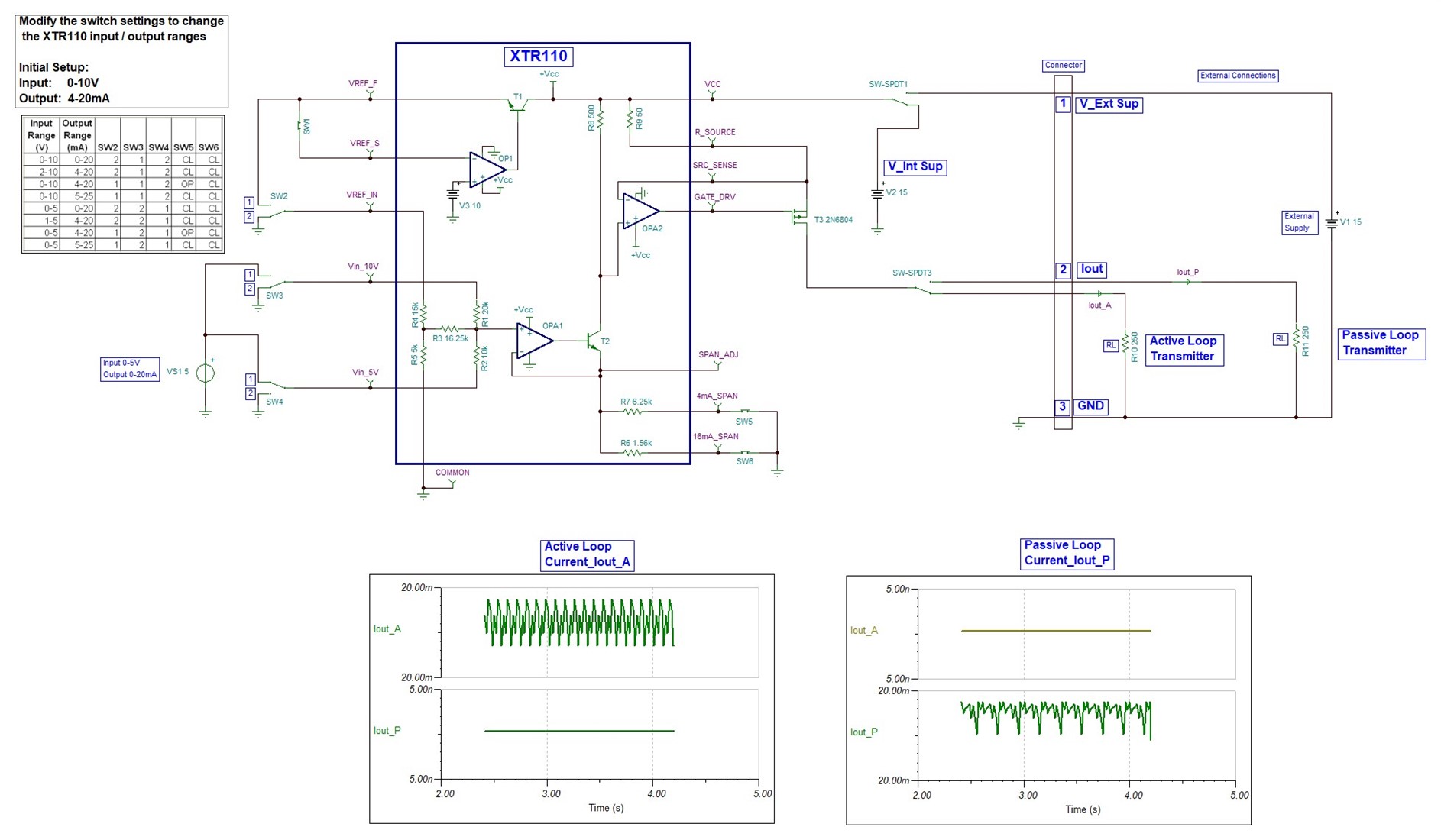
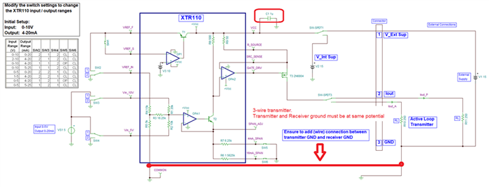
Regarding the XTR110 (3-wire) circuit, ensure that the transmitter XTR110 GND potential is the same as the receiver GND potential. Please add a third wire connecting the receiver and transmitter grounds together. This GND connection is also required if you select the XTR111 (3-wire) transmitter. Please also add a local supply bypass capacitor in close proximity to the XTR device.
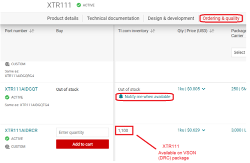
As you have mention, the XTR110 surface mount package is currently out of stock. The XTR110 (3-wire) is a legacy device from 1984. You could choose the XTR111 which is a newer device. The XTR111 (3-wire) is currently available on the VSON (DRC) surface mount package.
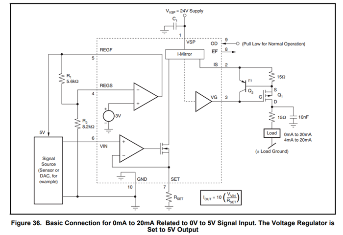
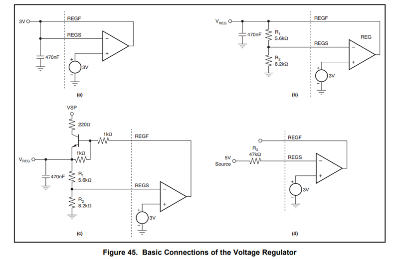
If you choose the XTR111, please follow the recommended circuit on Figure 36 of the datasheet. Also include a 470nF bypass capacitor on the regulator force (REGF) connection:
XTR111 Regulator Connections:
If you require notifications when a out of stock device becomes available, please navigate to 'Ordering & quality' and click on 'Notify me when available'.
Regarding the XTR110 (3-wire) circuit, ensure that the transmitter XTR110 GND potential is the same as the receiver GND potential. Please add a third wire connecting the receiver and transmitter grounds together. This GND connection is also required if you select the XTR111 (3-wire) transmitter. Please also add a local supply bypass capacitor in close proximity to the XTR device.
Yes sir i'll add.. is this connection only for simulation point-off view, bcz in schematic & layout point of view from board connector onwards all ground connections are shorted bcz i'm using only single GND notation.
So, As per your explanation i can use above 3-Wire circuit model for both Active & passive configuration with XTR111 device...
If you require notifications when a out of stock device becomes available, please navigate to 'Ordering & quality' and click on 'Notify me when available'.
Thank you for your suggestion to select device. but in my website it shows XTR111 VSON (DRC) package is in Out of Stock...
Unfortunately, I don't have additional information about device availability. I am part of the applications team, providing technical support but I don't have further visibility on device inventories. If the device you require is out of stock, you may request to be notified when devices become available.
We designed and Simulated the 0-20mA current transmission using XTR111 and Verified the Results also...
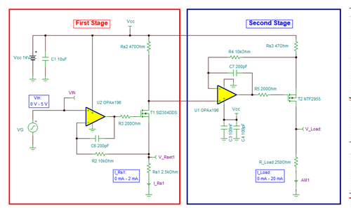
But Unavailability of XTR111AIDRCR stock.. Alternatively i have designed 3-Wire 0-20mA Transmitter using Full Discrete model as per TIPD102 Ref document..
So, As per the below attachment of the discrete design, can you please verify once and let me know if any modifications and give me the confirmation to go with production of this design..
However, keep in mind that the OPA2333 is a 5.5V maximum supply operational amplifier, and in your simulation, you show the device powered by a +12V supply.
You will need to modify the design and replace the operational amplifiers to support the +12V supply. An amplifier such as the OPAx197 or OPAx192 could work in the application.
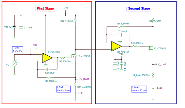
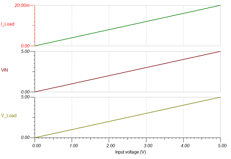
Below is a TINA file for a similar modified circuit using the OPA2192 I put together for a Customer a couple of years ago. It works for a VIN= 0V-5V signal, providing 0mA-to--20mA output, supporting a 12V supply. The design will work with the OPA2192 or the OPA2197. The OPA2192 and OPA2197 are both 10-MHz, 36-V, precision amplifiers offering the same AC performance, providing low offset and low drift. The only difference between the OPA2192 and OPA2197 is in the offset and offset drift specifications.
Please see below the TINA file simulation and simulation results.
We designed and Simulated the 0-20mA current transmission using XTR111 and Verified the Results also...This circuit we are placing as a Alternate circuit for V-I Converter discrete design (Discussed in previous message).
1) So can you please verify the attached Tina simulation file of XTR111 to generate the 0-20mA output with 0-5V input and Supply voltage is +12V.
And also we are going to use the DAC (DAC128S085) for generating the Voltage output to Current transmitters(0-20mA) & voltage transmitter (0-10V & ±10V)
2) In the XTR111 circuit we used Rin-10kohm. So can you please verify this also, if any requirement to change this Rin resistance as per the DAC128S085 output.
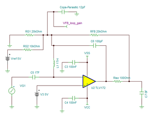
3) And i'm attaching one more design for generating the 0-10V & ±10V output using Opamp-TLV172. Can you please verify the simulation and let me know if any modifications to be done.
The design will work with the OPA2192 or the OPA2197
As per your suggestion we are using the OPA2197 for 0-20mA discrete design but OPA2197 & OPA2192 stock is not available.. can we use TLV2172 in place of OPA197 or OPA192..other wise shall we find similar specification of OPA192.
It appears a number of the questions below are related to different circuits, each with their own different requirements, and these are no longer directly related to the original post of the XTR117 or the XTR111. You may need to open a new query if you need information about the DAC128S085 or the other circuits, so you can connect with the appropriate applications engineer. I attempted to answer some of your questions below, but you will need to submit new queries if you have more questions that are no longer related to the XTR111 or XTR117...
We designed and Simulated the 0-20mA current transmission using XTR111 and Verified the Results also...This circuit we are placing as a Alternate circuit for V-I Converter discrete design (Discussed in previous message).
1) So can you please verify the attached Tina simulation file of XTR111 to generate the 0-20mA output with 0-5V input and Supply voltage is +12V.
The basic XTR111 circuit will work supplying a 0-20mA or 4-20mA output current into 250-Ohm load without issues while powered with a +12V supply as you shown on the simulation below.
Among the 4-20mA current loop application notes and links I provided above, there are a few detailed examples on 3-wire current loop transmitter reference designs incorporating the XTR111 that may be of interest for your review. These reference design provide suggestions of protection circuitry and XTR111 protection diodes that could be of interest depending on your application requirements. Please review:
2) In the XTR111 circuit we used Rin-10kohm. So can you please verify this also, if any requirement to change this Rin resistance as per the DAC128S085 output
Per the DAC128S085 datasheet, the device can provide a full-scale output of typically 4.955V when powered with VA=5V while driving about 1mA current. If you need to reach 5V, you may need to power the device with a +5.5V supply or a voltage around >+100 millivolts above +5V (VA>5V) to avoid the DAC output headroom limitations. The device will have no issues driving the 10kOhm load.
If you have questions specific to the DAC128S085 requirements, please open a new query/request on the Data Converters Forum and the DAC18S085 application engineer specialist will be able to assist you.
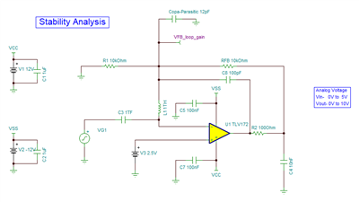
3) And i'm attaching one more design for generating the 0-10V & ±10V output using Opamp-TLV172. Can you please verify the simulation and let me know if any modifications to be done.
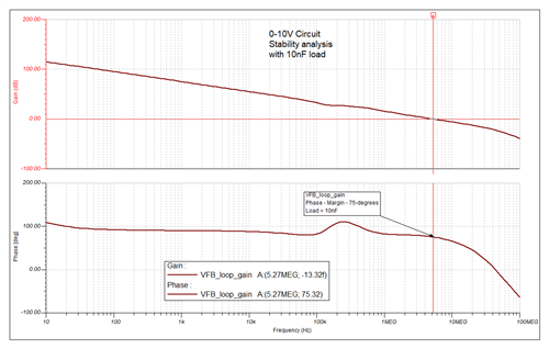
A quick open-loop AC stability analysis check shows the circuit 0-10V is stable (stable for a 0nF to 10nF load).
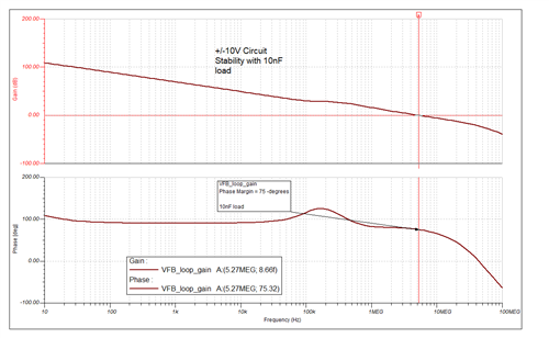
Similarly, an open-loop AC stability analysis check shows the circuit of ±10V is stable while driving a 0nF to 10nF load:
The circuit overall will work, I made an assumption that this is for a 0nF to 10nF capacitive load. Depending on the total load impedance: max capacitance, inductance and resistance, you 'may' need to compensate differently depending on the impedance requirements related to the application.
If you wish to learn about stability analysis, you can review the resources below:
If you have more questions about these circuits, please submit a new query so you can connect to the appropriate applications Engineer supporting the TLV2172.
As per your suggestion we are using the OPA2197 for 0-20mA discrete design but OPA2197 & OPA2192 stock is not available.. can we use TLV2172 in place of OPA197 or OPA192..other wise shall we find similar specification of OPA192.
The OPAx196 will also work in this configuration.
The TIPD102 Reference Design User guide documents in great detail the design procedure. Since this is your design, you can also follow the given examples and check the circuit on your side as well.