This thread has been locked.

If you have a related question, please click the "Ask a related question" button in the top right corner. The newly created question will be automatically linked to this question.

OPA2317: Switching the amplifier power

Part Number: OPA2317
Other Parts Discussed in Thread: ADS1220, INA322, INA321

Good morning team, 

I have a question about powering and depowering the amplifier dynamically.

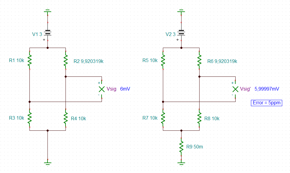
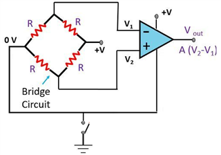
I am already using the OP2317 in a bridge measurement circuit, as a low o/s instrumentation amplifier at the output of a strain gauge.

I currently switch on and off the bias to the resistor bridge (1Hz up to 128Hz depending on customer choice of sample rate) in order to save power - it's a low power battery application.

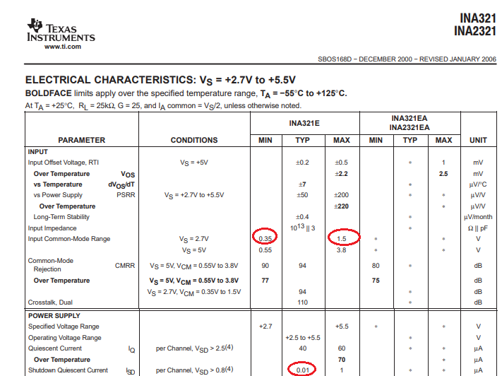
Would I run into problems of reliability switching the power to the amplifier as well?  The equipment might be running for a number of years, so this would quickly escalate to billions of power cycles over life.  I note a couple of specifications in the datasheet.

1. Signals at the input must not exceed 0.3V of the power - the bridge power is also switched, but it's switched on the low side (for inexpensive low Rds_on FETs).  This would mean that I would also have to low-side switch the power to the amplifier otherwise the inputs would be connected to a voltage of 3.0V (the bridge supply) and around 300µA per input would be drawn through the internal protection diodes as the bridge resistors are all 10k.

2. The typical turn on time is 100µs - there is no maximum specified but I would propose that 10ms is a pessimistic value.  For this reason (and because I would wait for this period so as not to degrade accuracy by using the amplifier before it's working properly!) I would only switch on and off the amplifier for settings of 16sps (16 power cycles per second) and lower.  There will also be wasted energy associated with charging and discharging of the amp's decoupling capacitors, and the input capacitance of the following ADC, however small.

It doesn't feel right, but I guess devices like the ADS1220 have an internal PGA which gets switched on and off between conversions the same number of times over life...

Is there another way to reduce the operating current, between samples, that I haven't thought of?  I know it's only 20-30µA but our power consumption is critical.

thanks & regards

David

  • Further searching for a suitable part has led me to the INA322 which looks like it can be shut down and re-enabled pretty swiftly.  That would seem like a better choice if I can put up with the offset.

  • Hi David,

    be very carefully when switching the bridge voltage. The voltage drop cross the on-resistance of switching MOSFET can considerably degrade the precision. See this thread:

    https://e2e.ti.com/support/amplifiers-group/amplifiers/f/amplifiers-forum/1116332/ina333-application-inquiry

    Kai

  • Hi Kai,

    many thanks, but I don't see any mention about low side switching of the bridge in that link, it seems to be a thread about switching regulator noise on the bridge supply and correct choice of reference for the instrumentation amp.  I'm relatively unconcerned about the error introduced by the FET - I've been using a FET with Rds_on of around 50mOhm, and the bridge resistance is 10k.  That error will be dwarfed by the amplifier gain setting resistor tolerance (0.1%) and inherent errors in the mechanical bridge.  I can calibrate most of these out during production.  My primary concern at the moment is achieving power reduction.

    cheers, Dave

  • David,

    Your scheme of shutting down the resistive bridge and op amp with a FET switch MAY work BUT you must take into account the Roff resistance of the switch (it's not infinite). Since the shutdown is accomplished by the voltage drop across the switch, it will take certain amount of the leakage current for the voltage to rise on the negative supply pin (low side of the bridge); if you assume FET Roff of 1Mohm, in the worst case there would still be ~3uA flowing in the bridge draining your battery. Using INA321 may be a good solution - please be aware that the INA321 minimum supply voltage is 2.7V and the linear input common-mode voltage is from 0.35V to 1.8V (for Vs of 3V) - see below.  Having said that, with INA321 typical shutdown quiescent current of 0.01uA, this would be equivalent of Roff resistance of 300Mohm. However, in order to minimize draining of battery, you will still have to deal with shutting down of the current across the bridge, which may require a FET switch in series with the battery, anyway.

  • Thank you for drawing my attention to the FET, you're quite right, the device in the design currently has 1uA leakage at 25°C and 10uA at 55°C!  Shame on me I never thought to check...

    The common mode range is more of a problem.  The bridge is symmetrical, so the operating point is around 1.5V (half of my analogue supply of 3.0V) with about ±50mV of signal movement, plus gain and offset errors due to component tolerances on top.  I might just squeeze inside the 1.8V limit ... otherwise I need to magic up a higher voltage supply rail for the amplifier, or I'm going to have to drop the bridge bias voltage with a corresponding penalty on SNR.

    Thanks for your help Marek!

  • Ok with these values the error would only be 5ppm:

    Kai