- Ask a related questionWhat is a related question?A related question is a question created from another question. When the related question is created, it will be automatically linked to the original question.
This thread has been locked.
If you have a related question, please click the "Ask a related question" button in the top right corner. The newly created question will be automatically linked to this question.
I would like some discussion of a dual INA1620 headset driver circuit version of this, higher supply voltage, compared to an op amp/BUF634A approach (possibly using two BUF634A's in parallel).
There are several circuits on the net for each approach. Not sure what to use for the op amp with the BUF634A 's- seen AD844, OPA1622, OPA1688, OPA134, etc. I'm thinking I will need more power than this circuit is providing but supplies may be limited to +/-12V or so. I'll likely purchase the eval boards for each chip.
Barry,
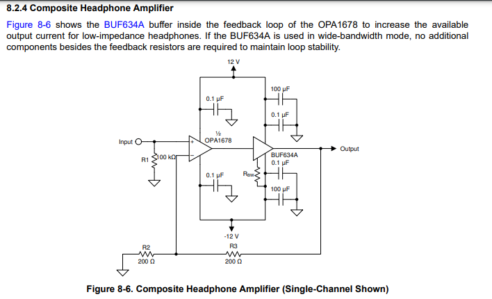
You could potentially use a composite and parallel solution with the OPA1678 and the BUF634. Have you seen this circuit in the OPA1678 datasheet?

Best Regards,
Chris Featherstone
I got overwhelmed by the number of different op amps used in this application. Each different and I couldn’t really tell why they were chosen as some are older than others. I had not come across the OPA1678 but I’ll check it out.
Hi Barry,
what is the load resistance of your application? And what output signal amplitude is wanted?
What is the load capacitance? Cable? How long?
Does the application allow some isolation resistance at the output of amplifer? Some headphones do specify this.
What about short circuit protection of amplifier?
What setup does the manufacturer of headset recommend?
Kai
Barry,
Yeah, there are several ways to approach this. It can be overwhelming with so many things to consider. If you can provide some of the design targets, we can help guide you in the right direction.
Choosing the right Op amps will depend on design targets you are trying to reach. There are a few key items to look at such as noise performance, THD, input common mode range, output swing and current drive capability.
I would start by identifying the current drive, output voltage swing and load resistance you need to drive without going into current or voltage limit. Essentially identifying the output power capability you need.
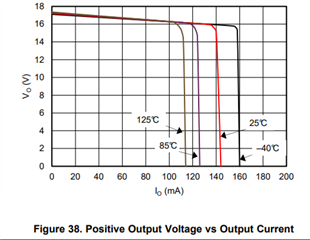
As an example of output current limiting, we can see from the INA1620 product datasheet Output voltage vs Output current plot that at room temperature the device will go into current limit around 140mA. This will result in the output waveform clipping and distortion will be present. In this case you may consider a parallel solution if you need more current similar to our Application note for this device that can be found here:

I have recently built this circuit on the INA1620 EVM with some wiring soldered to the evm pads in order to create the parallel solution. It sounds very good!
The INA1620 is effectively two OPA1622 devices with precision matched resistors on the die. This precision matching provides two benefits.
If your application doesn't require the high fidelity of the INA1620, you may consider another approach such as the OPA1678 combined with the BUF634. The OPA1678 is a great device. It does have lower output current capability than the INA1620 and lacks the integrated resistors. It has a cost advantage, slightly lower Iq and much lower Ib. You are still getting great audio performance.
Best Regards,
Chris Featherstone
Aviation headset impedances vary - 600/300/19/8 depending on if it is a stereo or mono headset. Most applications are mono but stereo may be the future. Military aircraft applications can have much louder ambient environments than civilian aircraft so may really need to blast out the audio. I hadn't thought about cable length or short circuit protection yet. Old circuits I have seen didn't seem designed for it. I won't have the high voltage I would like (like +/-18V). More like +/-12V which limits to around 8Vrms output. Currents can vary to over 350mA depending on what's connected and how loud it must be. But I'm not sure if we will end up needing to support this. So if the INA1620 sounds noticeably better than the BUF634A approach it will be a worthwhile demo one vs the other. Another factor is heat dissipation. I have never had to worry about this before. Another interesting realization - the most popular headset used for something like this is the Bose A20. It has a low frequency filter and high frequency filter to optimize to just voice communications. Play music through them and you notice less HF hiss and low end vs audiophile headsets. Old tried and true amp circuits used an op amp with two transistor buffer and worked fine. Its debatable whether good audio performance of this amplifier improves communications. Something I want to see/hear for myself.
One thought. If the system this headset driver were to be part of is to be spec'd at -40-125C would the audio characteristics be expected to meet spec throughout? Jeez I'd have to use 3 or 4 BUF634A's!
Any idea what it is about the INA1620 that makes it sound better than the BUF634A approach?
Barry,
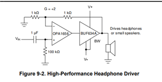
Considering over temperature, the Vout vs Iout curve will show reduced current drive capability at hotter temps for all the devices. This would be one line item to look out for to ensure you have enough headroom over temp. The INA1620 is a very high end device with better 1kHz noise of 2.8nV/rt(Hz) vs the OPA1678 4.5nV/rt(Hz), better CMRR performance and current capability. The sound quality is definitely subjective and getting specs of even the OPA1678 combined with the BUF634 will still render very high quality results. You may even consider the OPA1656. It has better noise performance than the OPA1678 and also makes for a good combination with the BUF634A. Given that you will be driving a cable and will need high output current drive I think this may be a great option for you to try. The BUF634A shines with it's high cap load drive and combined with a precision amplifier in the fashion shown below you will decouple the the thermals generated by the BUF634A and maintain the precision offset voltage of the front end. You would basically be getting the great THD and noise performance and replace the output stage of the precision amp with the BUF634A to do the heavy lifting of driving the headphones.
You would probably have to be in a listening room to be honest to hear differences at the levels we are discussing. There is definitely strengths to each of the devices and I think the biggest concern will be cap load drive and current capability that is required.

Best Regards,
Chris Featherstone
I will likely be using a +/-12VDC supply. Unless there is a trick voltage booster circuit it will limit the power to higher impedance headsets. Sometimes a user will wear earplugs to reduce the ambient noise (machine gun or whatever) and then the headset has to be normally painfully loud to surpass the ambient noise. The headset amplifier circuitry is preset for the type of headset used. Some kind of pre-detect circuit that recognizes the impedance of the headset would be nice but I haven't found this. I think some companies have this but its not in public domain. I don't have an answer on cable length - think the length of a cargo area I guess. Short circuit protection would be necessary. Several different headset possibilities - I don't find any suggestions for use in their documentation.
I have ordered parts to try several of these suggestions. It will be interesting to "see" if there are meaningful audible differences.