INA1620: INA1620

Part Number: INA1620

Tool/software:

Dears,

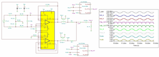
At present, in the process of debugging, testing and aging when INA1620 is used, the operational amplifier becomes overheated, the background noise becomes larger, and the distortion becomes larger. Would you please help to check whether there are any problems in our design drawings or can we optimize them

INA1620 Schematic.pdfINA1620 Issue summary.docx

  • Hi Li Ning, 

    I am reading your report in Chinese. I need to understand some of the issues before I can comment on the issues. I am the only one that is able to read your report in Chinese from the team (unless use translator). Please confirm the following. 

    1. You are using switching power supply. What is the switching frequency and ripple voltage at the INA1620's supply pins? 

    2. It looks like your power supply has a switcher and further regulated by SGM's LDO, what is ripple voltage after the LDOs. Do you have FFT spectrum on your power rails (+/- supply rails). For audio application, the high frequency ripple voltage should be <1mVpp. In other words, clean no ripple power source.  

    3. INA1620 is powered by ±5Vdc? what is the load impedance for the INA1620's output. I want to know how much current it drives and I can calculate what is the heat dissipation in INA1620. There are two op amps per IC and I need to calculate the total heat dissipation. If one dissipate 0.5W, total is 1W. 

    4. What is the thermal pad is connected to? It should be connected to V- or lowest voltage on your PCB. I see that there are many thermal via, but it needs to be connect to large V- power plane to dissipate the heat. I would recommend to use 2oz copper (should be more than 1oz Cu). You need to increase the Cu dissipated area to remove the dissipated heat. 

    I have a feeling that you do not have enough dissipated Cu area to remove heat away from INA1620's thermal pad based on the picture so far.  

    5. Based on the report, it looks like the soldering is done by hand. You mentioned that you had soldering issues. You think that your soldering issues are resolved, not you are looking for INA1620's performance issues. 

    6. Please confirm that you are not violating the input Vcm and output linear operating region. What is the output impedance load, 600Ω or something else?

    7. When you troubleshooting your circuit for the first time, you need to start at lower voltage and gradually increase the supply rail. You should limit the supply's output current and check for the operating state. Do not turn on the DUT at the full power and hope for the best. 

    Please get a current probe and capture the audio voltage and current waveforms. It seems that you are overdriving your load.  

    8. is this 2 layer PCB design?  

    Please get back to me the information, and I will try to simulate your circuit. 

    E2E is a public forum. If you prefer the privacy, you can request for "friendship" connection to my E2E profile. We can support the application in a different platform. 

    Best,

    Raymond

  • Hi Li Ning,

    For the precision audio application, INA1620 should be connected similar to the follow manner. The input and output impedance have to be well matched in order to optimize distortion and reject common mode noise. The input is feeding into non-inverting high impedance node, and it is configured like instrumentation amplifier, see the attached schematic. 

    Here is the Tina Simulation.

    INA1620 Overheating Issue Option2 12072024.TSC

    I think that you are doing the following, which is paralleling two op amp to drive the audio application (you want to double the output current). 

    https://www.ti.com/lit/ab/sboa553a/sboa553a.pdf?ts=1733526321801

    If you have other questions, please let me know. 

    Best,

    Raymond

  • Dear Raymond,

    Pls kindly help find attachfile with customer reply,thanks.

    FIIO Reply-1210.xlsx

  • Hi Li Ning, 

    I read your xcel document. 

    电源纹波已超过高质量音响运放设计指标. I assumed that the scope shot is captured under light or no load condition. You have to measure the ripple under the full loaded conditions, and get rid of high frequency noises. For high quality audio application, the ripple voltage of  ±5.5Vdc supply has to be <1mVpp and filter out all ripple and harmonic noises.  

    Use LDO may help, but typically LDO's PSRR works well for low frequency only, say <10kHz (>80dB). Near 100kHz or greater, PSRR is reduced to 20-30dB or lower, which it does not attenuate the ripple noise effectively. 

    设计输出负载:16Ω~300Ω,典型平衡并联输出最高950mW/32Ω。I do not like the audio topology. If you want to source/sink higher amount of current, you need to use different type of amplifier configuration, like BUF634A. Parallel INA1620 will increase the output current, but this is not the design configuration for audio application. 

    品质会使用最低6Ω的耳机听音 - I am not sure that BUF634A is able to drive the low impedance. You will have poorer performance and lot of distortion when volume is increased. 

    目前PCB板厚度0.8mm,长宽60mmX27mm,8层PCB,铜厚1安司。- we have to calculate the INA1620's power dissipation first under the worst case operating condition. What is the highest Tamb for the application. 

    使用回流焊机器自动焊接 - reflow process for typical IC is designed for no more 3 times approximately. Yes, degradation may occur. 

    https://www.ti.com/lit/an/spraby1a/spraby1a.pdf?ts=1733842669461&ref_url=https%253A%252F%252Fwww.ti.com%252Fsitesearch%252Fen-us%252Fdocs%252Funiversalsearch.tsp%253FlangPref%253Den-US%2526nr%253D101112%2526searchTerm%253Dmsl

    我们的方案是按照提供的参考资料设计 - which design reference.  Are you referring to the following design reference. However, your load is much higher than the intended application. 

    https://www.ti.com/lit/ug/sbou205/sbou205.pdf?ts=1733842947376&ref_url=https%253A%252F%252Fwww.ti.com%252Ftool%252FINA1620EVM

    https://www.ti.com/lit/an/slma002h/slma002h.pdf?ts=1733845143434

    使用运放内部电阻做反馈,是否能承受80℃的温度?Yes, the INA1620 is rated to the following Tamb conditions. If IC's Tj is not exceeding 125C, the degradation will be the minimum when operating at higher temperature. The max. Tj in this part is 150C. Try to avoid high Tj operating temperature, if you are able. However, it is the best to keep the Tj as low as possible for a given Tamb operating condition. 

    If your casing is constructed in metal, say aluminum, it will be good to provide a thermal path to the casing, increase the dissipated area and lower the INA1620's PCB and/or Tj temperature.  The onboard 1kΩ resistors are matching resistors (not absolute 1kΩ value). You need to use these in pairs (ratiometrically).  

    热焊盘为负压,是否需要跟芯片负压引脚直连?

    如图测试输出OK的波形。正常底噪6uV。≥信噪比100dB - I do not understand this capture shot. If this is ripple voltage on your ±6.2Vdc, then your power supply is not filtered out properly. If your audio application is operating between 100Hz to 20kHz, then your ripple frequency should be filter out below 10Hz or lower and ripple voltage has to be low <1mVpp at 10Hz or lower. Otherwise,  the significantly amount of switching harmonics will be inside of audio frequency band. If this is not audiophile application, this may be acceptable, then you may not need to have INA1620 high grade amplifier to drive it. 

    Let us resolve your high temperature operating issues. I need to know how much power dissipation you are driving under nominal conditions, and what is the worst case design requirements. 

    Best,

    Raymond 

  • Dear Raymond,

    Pls kindly help to check customer feedback,thanks.

    FIIO Reply---20241211.docx

  • Hi Li Ning, 

    Ok, I see that the application note. 

    https://www.ti.com/lit/ab/sboa352/sboa352.pdf?ts=1733961364507&ref_url=https%253A%252F%252Fwww.google.com%252F

    I will simulate the power dissipation in INA1620. The INA1620 can drive up to ±100mA, but the output current per channel should be limited to approx. ±80mA. Per INA1620, the output current should be limited to ±160mA. Beyond the output current, you are going to see distortion and overheating, which are not ideal for the audio application (in addition to good heat dissipation). 

    问题是测试或者老化一段时间后出现不可逆转的劣化 - I am not sure what the aging means in the context. The part should have at least 1000 hr of life span, if it is operating at 125C (Tamb). 

    Best,

    Raymond

  • Hi Li Ning, 

    Sorry for the late reply. 

    The power dissipation on 32Ω impedance load is approx. 190mW, see the simulation. Outside of the +/-4V input Vcm range, the part will start to distort the output signal. 

    INA1620 Parallel Topology PD 12122024.TSC

    Based on the 0.2W power dissipation, you should have Tj = Tamb + 13.1C/W * 0.2W = 25C + 2.62C = 27.62C. 

    If you are doing 0.9W per your special application, Tj = 25C + 13.1C/W*0.9 = 36.8C, which it still seems to be ok. But this is assumed that the built up heat in INA1620 is able to dissipate through the PCB copper clad, and you have enough surface area to dissipate the heat properly. 

    For 900mW, you have to increase Vcc and Vee in order to increase the power (or lower microphone's impedance).  Notice that I used AC coupled output, since the audio application does not need to drive DC signal. If the microphone is coupled directly without the capacitor, then it will dissipate more heat. I do not see impractical issues with your existing setup, if you take care of soldering issues and leakage path. If the application's Tamb is operating at room temperature, I do not see why you will have exceed 80C on the surface of INA1620 (Tj will be higher than the IC's top surface by 13.1C*1W or 1.3W). Please monitor the supply's current and see what is causing the IC to have the high temperature rise above Tamb. 

    I see that you placed a Al plate with thermal conductive adhesive on top surface of the INA1620. It will help to lower the IC's surface temperature. However, over 80% heat is dissipated through the thermal pad, which it will require to increase the surface of thermal dissipated area via PCB Cu layers. So this is likely the area that your revision may need to improve. 

    Please let me know if you have additional questions. 

    Best,

    Raymond

  •   Hello, I am a hardware development engineer and use Ning's number. At present, it is not a question of how much output, and the output of 900mW has been evaluated at the time of the DEMO board. Heat dissipation problems we have plus heat sinks. At present, whether it is in the light load or heavy load test, 15 machines, the function is unstable, more than 50% of the op amps are suddenly hot, overcurrent, distorted, and unstable. Whether the circuit can improve and optimize these problems, such as adding ground resistance according to the input of the circuit you simulated, and the pins that are useless for the internal resistance of the chip, we are currently suspended, whether we need to connect according to the circuit you simulated.

  • 输出信号后,一个芯片升温,过流异常。暂停输入信号,或加热过流,芯片无法恢复正常。它需要重新开机才能恢复正常。

  • After the output signal, one chip heats up and the overcurrent is abnormal. Suspend the input signal, or heat overcurrent, the chip can not return to normal. It needs to be re-powered on to get back to normal.

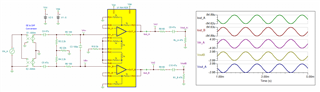
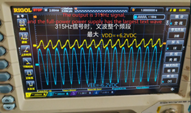
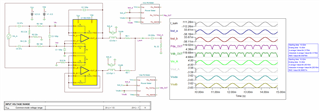
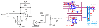
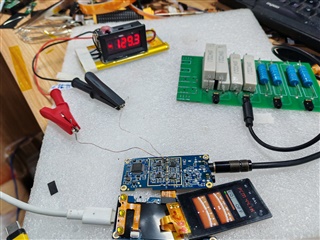
  •  The output of the left channel is distorted, after heavy load, when the input is turned off, the current at the USB end is still 0.54A, and the normal should be 0.25A, at this time, the U12 chip is hot, and the test U12 positive voltage supply current fluctuates around 80 to 130mA, and the normal static current is only 5.3mA. After the chip cools down, it can return to normal after re-powering on, and it cannot return to normal after several tests may be due to the heating has not cooled down. In the case of no power failure, the quiescent current is large, and the fan blows the current and cannot come down.

  • Hi Li Ning, 

    How many units that have the latch-up issues (overcurrent or over temperature)?

    I am not aware of the overcurrent latched up issues in INA1620. Have you tested the same circuit in INA1620EVM?

    https://www.ti.com/lit/ug/sbou205/sbou205.pdf?ts=1734455271174&ref_url=https%253A%252F%252Fwww.ti.com%252Ftool%252FINA1620EVM

    It is the best way to have a call. Please submit "friendship" request via E2E forum and I will find to way to reach you once the communication is established. Or you can contact our AFE in Shenzhen and we can go through the communication via the route. 

    The video idea is helpful, but you are showing me the DC information. I need to know what is AC is doing, and I need to understand which the circuit configuration you are operating. If you are working with damaged IC, I have no ways to know. Let us sync up with your setup first, then I can troubleshoot what is going on. 

    Best,

    Raymond

  • Hi Li Ning, 

    I do not know how your 900mW is calculated. I am unable to simulate INA1620 with 0.9W dissipation with +/-5.5Vdc supply rail and 16 ohm load. Please keep in mind that the total output current from INA1620 can not exceed +/-200mA with parallel configuration. 

    Best,

    Raymond

  •    Dear Raymond,

       At present, after debugging, after turning off the enable of the parallel follower op amp, use a heat gun at 120°C to heat another set of non-following op amps, and the load output is normal with different amplitudes. After turning on the enable of the follow-up op amp, the output amplitude of the load connection is only a few tens of millivolts or less, light load, heated by a heat gun, to more than 80 °C, the output is abnormal, or the distortion is large, or there is no output, or overcurrent. It has been determined that the parallel topology circuit is unstable. Please help check how the circuit needs to be optimized, whether the resistance accuracy and capacitor accuracy are affected? Does the gain setting have an impact? Thank you.

  • Hi Li Ning, 

    Please help check how the circuit needs to be optimized, whether the resistance accuracy and capacitor accuracy are affected?

    Please try to match the 0.5Ω or 1Ω resistors with tolerance at 1% or better. If the resistors are not matched well, it is possible that there are larger current flow between two output nodes. 

    The sand casted resistor likely has tolerance over 5% or higher which it may not be suitable for driving the load in parallel. When resistor heats up, it has different temperature coefficient (TC) as well. The difference of TC may cause the issues. 

    You mentioned that 50% of the circuit has the issue. What happened to other 50% - please describe in details when we communicate over the phone.  

    We are entering the holiday seasons in U.S., and I suggested to have a call before we are going to holiday break. Please let us know. I have provided the E2E "friendship" request in the previous email. 

    Best,

    Raymond

  • Hi Li Ning, 

    In addition to matching resistor, please remove the snubber to see if the power dissipation is decreased. I think that it might be the high current dissipation issues. Please let me know. 

    Best,

    Raymond

  • Dear Raymond,

         After following your suggested changes, there is no improvement. Once the parallel mode is connected, the output is unloaded, and the load may be distorted, and the chip will be hot and overcurrent. Heat over 80°C with a heat gun to reproduce the problem 100%. Remove the parallel follow-up part, no problem, I will draw the circuit used into Tina, please help with the simulation and analysis.

  • Parallel mode, two channels, not the same op amp, will this have an impact?

  • Hi Li Ning, 

    Parallel mode, two channels, not the same op amp, will this have an impact?

    In op amp parallel mode, two op amps need to be matched in terms of Vos, output impedance and current source/sink level. Otherwise, the total output current is not going to be shared between the op amp drivers. 

    Once the parallel mode is connected, the output is unloaded, and the load may be distorted, and the chip will be hot and overcurrent. Heat over 80°C with a heat gun to reproduce the problem 100%.

    I have gone through the simulation that you sent. There are no issues with the circuit (if the output stage is not over-driven).  The parallel INA1620 circuit has been verified over the lab and it should work as simulated (by audio engineer). 

    I also verified that the total simulated circuit is 0.916W with 32Ω resistive load per our simulation. Each INA1620 package is dissipated 0.916/2 = 0.46W.  which the IC should be able to withstand the heat dissipation, IF THE IC'S HEAT IS DISSIPATED PROPERLY.

    FIIO INA1620 Overheating Power Analysis 12212024.TSC

    In the shutdown mode per the INA1620's datasheet, here is a part of capture. I was wondering if you are encountering similar events as described in the paragraph. Please play around the shutdown sequences when parallel the output stages in the part. 

    I recalled that you mentioned that ~50% of INA1620 is "working". Can you tell me more about the "working" units. Are there all behaving in the similar manner? In unparalled mode, the INA1620 op amp is working properly. The issues are when the INA1620's two op amps are placed in parallel mode. 

    Best,

    Raymond

  •  Dear Raymond,

    1、 In op amp parallel mode, two op amps need to be matched in terms of Vos, output impedance and current source/sink level. Otherwise, the total output current is not going to be shared between the op amp drivers. 

    This one is making a test board, and the parallel op amp uses the same chip to use the verification

    2、I recalled that you mentioned that ~50% of INA1620 is "working". Can you tell me more about the "working" units. Are there all behaving in the similar manner? In unparalled mode, the INA1620 op amp is working properly. The issues are when the INA1620's two op amps are placed in parallel mode. 

     There may not be every machine tested all the time, for example, 4 machines are tested at a time, two of them have problems first, and the other two are frequently used later, and there will still be problems at irregular times, so at present, basically every one has a probability of having a problem.

  • Hi Li Ning, 

    You may reply it in Chinese. I am not quite sure that I understand your reply. 

    so at present, basically every one has a probability of having a problem.

    I am not asking for the probability. I'd like to know does every unit have the common over current issues when the load is removed. 

    I need to rule out if you are working with a good INA1620 op amp vs. problematic one. 

    Best,

    Raymond