Hello,
I've both simulated and tested a TIA cuicuit using OPA657.
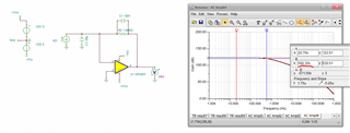
Based on calculation formula
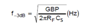
GBP_657 = 1.6GHz, RF =1.5MHz, Cs = Ccm+Cdiff+Cdiode+Cpcb = 20.5pF
The BW shall be 2.87 therically.
And a 1uA/3us pulse current can be shown on the TIA output shown by the simulation.
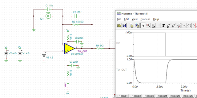
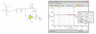
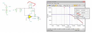
But when I test with the circuit board. The TIA output seems deformed caused by less bandwidth.
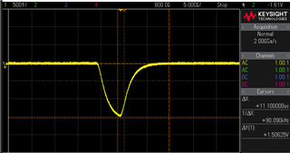
Unit I extend the light pulse to around 20us than the square wave shows up.
The photodiode itself has a 15pF parasitic capacitor and the datasheet says "Cutoff frequency is 250M at RL= 50Ω."
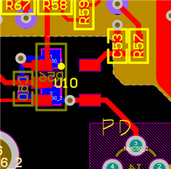
So I'm just wondering: Does my design (such as PCB layout, see below, U10 is the OPA657) causes the deformation or the bandwidth of the photodiode does?
And currently I don't have a signal puse generater to test my circuit.