This thread has been locked.

If you have a related question, please click the "Ask a related question" button in the top right corner. The newly created question will be automatically linked to this question.

BUF634A: Should there be a cap in series with Neg input resistor?

Part Number: BUF634A
Other Parts Discussed in Thread: OPA2810, OPA810, OPA1656, INA1620, OPA1655

I am used to seeing a cap in series with t he negative input resistor on AC/audio op amp circuits.  Why no such cap with this part? I also had another question elsewhere here that the eval board has a capacitor option across this resistor rather than series.  Don't see that done either.

  • Its a buffer with 1 input and 1 output, what do you mean? A schematic with where you want the C would help a lot - and yes, most audio app include blocking caps at least at the output. That is always an option on a general purpose buffer or op amp

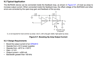
  • Take a normal non-inverting op amp circuit, break the connection at the output and put this buffer part in series, then feedback resistor from its output to the neg input of the op amp.  (I don't know how to cut/paste here)

  • Oh, so you are trying to to a power boost inside the loop. You can't put a cap in that loop or it won't find a DC operating point

    If your interest is Audio, I eventually go to this topic in a series of articles for AudioXpress. That list is in this file, 

    3718.Summary artilce list for AX series.xlsx

  • Hi Barry,

    click on the "insert" button of the input box and click on "Image/video/file".

    Kai

  • No, its been so long that I worked with op amps... the cap is in series with the neg input resistor when used in single supply designs - if bipolar the resistor goes to a ground the same potential the pos input resistor goes to so no cap needed.

  • Hi Barry,

    so you mean a composite amplifier?

    Can you show a schematic?

    Kai

  •   

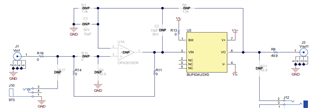
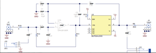
    This is one channel of the eval board schematic for the BUF634A. First I was wondering why there is a place for a cap at the C1 location.  Next I was asking if R3 should have a cap in series with it - but now realize it is not necessary.

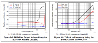
    A new problem I have discovered, that may kill the use of this part for me, is the rapid increase in THD at 10Vpp and beyond with low impedance loads.  I was hoping to possibly parallel two of these for use with 8 ohm loads.  Haven't checked it yet.

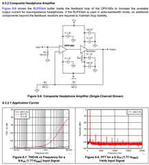
  • This is the circuit these plots apply to, not what you have drawn, 

  • No, it's the same.  I use 1K resistors as shown.  I had to move a bunch of 0403 parts around but same circuit.

  • Hello Barry,

    Just to clarify, your concerns are regarding the necessity/reason for certain passive components as well as the THD performance at low loads at/above 10Vpp?

    I can look into this for you.

    Best,

    Alec

  • Hi Barry,

    this EVM User's guide could way better explain what's going on in the circuit and on the PCB. When a "C1" can be seen in the schematic, on the PCB and in the bill of materials, it should be discussed in the User's guide as well. I cannot understand why this is not happening here.

    Because "C1" is sitting very close to the OPA2810, I think "C1" shall allow to HF decompensate the OPA2810, if wished, to partially compensate the HF compensation provided by "C2"?

    At least theoretically "C1" could also serve as an additional low pass filter cap at the input of BUF634A when setting the "DNP" jumpers accordingly (if OPA2810 is not mounted, of course). But for this purpose "C1" is a bit too far away from the BUF634A.

    Kai

  • So the circuit you put in I think was just the BUF634A EVM with all the optional stuff to add a OPA2810 (really the OPA810 as the OPA2810 is a dual) but showing all DNP. The 0ohm guys bypass that empty socket for just a buffer test, 

    When you add the input op amp, that local feedback C is used to hold stability - it is always an issue to add a power boost inside an op amp loop that also adds a lot of phase shift - risking instability and that local feedback C (C2 here) is used to provide local feedback at higher F. 

  • They could have done us a favor also by not using 0402 components on an eval board!

    I am using a OPA1656 instead of a OPA2810.  I did not see any instability as of yet.  I am getting a gain mismatch between the two channels that is weird.  I have a 100K resistor from the + inputs to ground and the signals feed into this pin by a .1uF cap.  I am measuring different resistance on this pin of each op amp to ground - one channel its like 68K, take the resistor out and the resistor measures 100K.  So I'll try swapping the op amp but jeez.  I think the C1 is just a screw up.  BTW, several people have published their headset driver schematics using this circuit without the C2 - but I can put one in and see if it changes anything.  Not unusual to have a cap here.

  • HI Alec,

    Yeah I posted a separate question on this one BTW.  I had looked at the specs with a main focus of output current capability and had missed seeing these two graphs.  It seems this is a voltage (not current) based behavior so I'm thinking that paralleling parts may not help.  For aviation headsets of 150/300 ohms to reach SPL requirements I need over 17Vpp.  For mono headsets I need twice this.  For first shot at this I am limited to a +/-12V supply so I may just begin to see this problem - but wondering what a second parallel chip would do.

  • Here is from the OPA165x datasheet:

  • I have lost track of where this is, might want to start a new thread since this one says it is closed. One caution, that schematic shows the BW control resistor - do not use that - want as much speed in the buffer as possible and that feature is not modelled in the 2020 TINA model for the BUF634A

  • Yeah they don't discuss this very well in the spec.  A lot of circuits show it tied to V-, but they discuss the resistor..

    I have another topic here about paralleling two of the INA1620 or BUF634A vs the THD Vpp graphs in the specs.  Looks like higher Vpp signals will have a lot of distortion and paralleling two chips won't help much.  I'm having a lot of newbie errors trying to use my QA401 to test this.  First off though I have a level mismatch between the two channels I am trying to fix.  Maybe an input of the OPA1655 got damaged?  Never seen this sort of problem with such a simple circuit. Hate working with the small parts too.