This thread has been locked.

If you have a related question, please click the "Ask a related question" button in the top right corner. The newly created question will be automatically linked to this question.

TLV7022: longer falling time comparing with other devices

Part Number: TLV7022
Other Parts Discussed in Thread: LM293, TLV7021, TINA-TI

Hi,

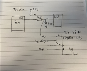
My customer is using TLV7022 as an input to the DSP and they found that the falling time of output (input of DSP) is about 2.7us and is longer than showed in datasheet, and also 600ns longer than competitor's devices.

Simplified schematic is as in the figure and two devices are drop-in replacement. My question is:

1. what possible reasons may cause the longer falling time of TLV7022? Could it be the difference Res of MOS on output stage?

2. what we can do to reduce this falling time, since it is much slower than the value in datasheet? 
Manu

  • What are the values of the components in the low-pass filter? I read 100 Ω and 10 µF, which would result in a time constant of 1 ms, which is obviously not correct.

    A low-power comparator does not have high drive strength. To reduce the effect of the drive strength on the falling time, use a higher resistor and a lower capacitor value.

  • Hi Manu,

    keep in mind that the TLV7022 is a micro-power comparator which you can easily short circuit by a too small filter resistance at the output.

    Kai

  • Hi Ladisch,

    Thanks for quick response, the capacitance should be 10nF. So do you mean if we want to have a shorter falling time we should reduce the resistor or reduce the capacitance?

    By the way, our customers were using LM293 before and don't have this issues, so the drive strength of LM293 is better than TLV7022?

    Thanks for your support!

    Manu

  • Hi Manu,

    in any case increase the discharging resistance. 100R is way too small. Then decrease the capacitance to your needs.

    Kai

  • The 100 Ω resistor and the output impedance of the comparator add up. If you change the LPF to use 1000 Ω and 1 nF, then the error introduced by the additional impedance is smaller relative to the resistor.

    The LM293 has indeed has a much higher drive strength.

  • Thank you, Clemens and Kai. These are all great inputs. 

    Manu,

    I hope these suggestions help with your issue. Let us know if any other problems arise. 

    -Chi 

  • Hi Ladish,

    Thanks for the explanation, one more question, for the drive strength of a comparator, which parameter can represent this, are the parameters showed in datasheet so me and customers can have a quick comparison?

    Manu

  • The worst-case drive strength is specified for VOL. Typcial values are shown in figures 16/17.

  • Hi Ladisch

    Could you pls kindly explain how this VoL represents the drive strength, I am not able to link this to drive strength. Also what means the "worst-case" ?

    By LM293 I could not find this kind of figure, so if I would like to compare this two devices, which parameters in LM293 should I focus on?

    Thanks a lot !

    Manu

  • VOL / IOL gives you the output impedance (i.e., resistance). A lower resistance is a higher drive strength. The typical resistance is roughly half the specified maximum.

    The LM293 datasheet shows the output behaviour in figure 6-3.

  • Thank you, Clemens, for the kind input.

  • Hi Manu,

    can you explain what you are trying to do? What is the aim of your circuit?

    Kai

  • Thanks Kai for the follow up. Will wait for Manu's response.

  • Hi Kai, 

    Thanks for helping and the support. In the former project we are using LM293's output as an PFC current protection signal input to DSP and if the signal goes low then it triggers the protection and turn off the IGBT of PFC circuit.

    However when we change the LM293 to TLV7022, the protection response time is slower than before. We found that the root cause should be the increased falling time/ the drive strength between two devices.

    So customers would like to know exact the output impedance of this two devices and do the comparison and have a specific explanation to this problem. That's why I ask for the data. 

    But I could not get a accurate value of output impedance under our using situation from the figure in datasheet, use case is 3.3V supply voltage and about 25C temp, output current should be around 0.15mA. Could you pls kindly share some data so that we can have a clear explanation to this phenomenon?

    Thanks a lot !

    Manu

  • Hi Manu,

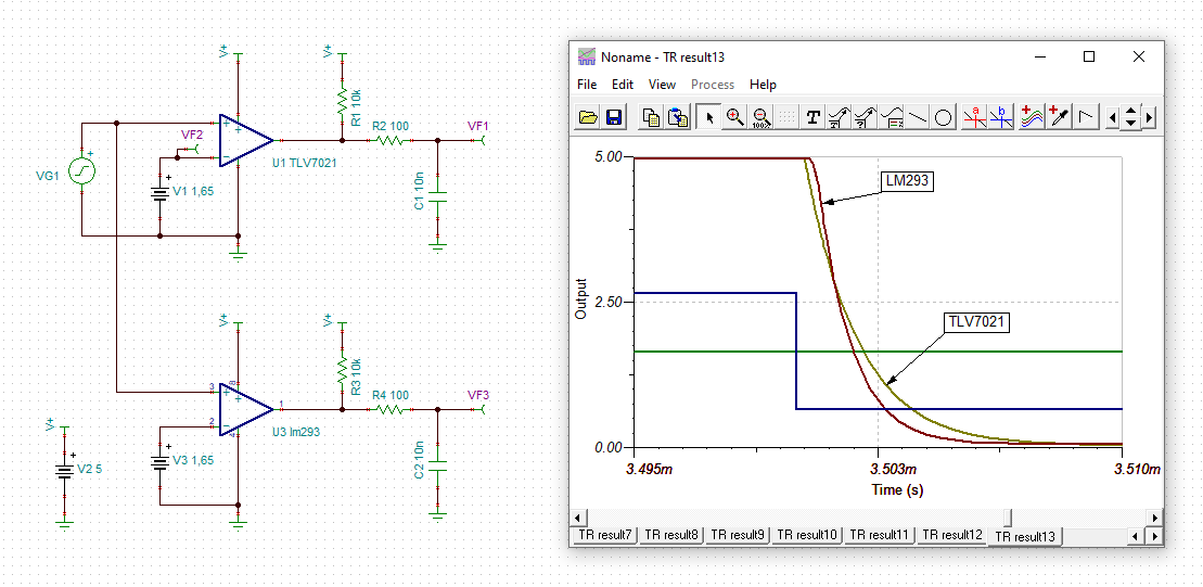
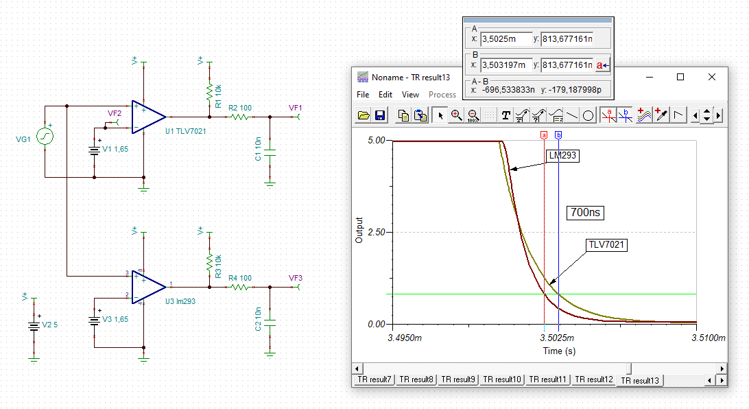
    I did some TINA-TI simulations and allthough I couldn't simulate the TLV7022 itself but only the TLV7021 and allthough I could only run a simulation at 5V supply voltage and not 3.3V (because the model of LM293 is only valid at 5V supply voltage), I think it can be read between the lines what's going on.

    manu_tlv7021.TSC

    Looks like the LM293 is a bit faster compared to the TLV7022.

    When you look carefully you will see that the output signal shapes differ a bit from each other. This has to do with the fact that the switching elements are different, an open collector NPN in the LM293 and an open drain NMOS in the TLV7022. The LM293 shows a somewhat higher switching delay at the beginning of the high-to-low edge but shows a lower "turn-on resistance". At the end of high-to-low edge the LM293 is about 700ns faster than the TLV7022.

    Kai

  • Thanks Kai. I just want to add that the models are just an approximation and I would rely on the datasheet figures and curves. 

    Manu, please refer to fig 16-17 for TLV7022 and fig 3 on LM293.  You can then estimate the output impedance from the VOH and output sinking current that you expect. Fig 26 in tlv7022 dataheet also shows fall-time vs load capacitances