This thread has been locked.

If you have a related question, please click the "Ask a related question" button in the top right corner. The newly created question will be automatically linked to this question.

Is it possible to use Cf to reduce the high freq. noise?

Part Number: THS3491

Hello. Experts,

Thank you for reading my thread.

I'd like to ask you something regarding the THS3491 application.

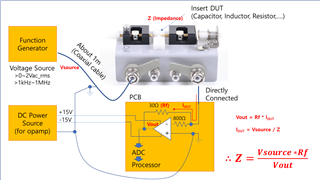
I designed and now I'm testing some pcb like a circuit above.

The purpose of this circuit is, 

We 'd like to sensing the current when we applied the AC Voltage(Vi) to DUT(C). 

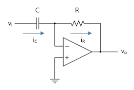
I thought, It would operates like transimpedance amplifier, so we can sense the current without delay.

But, now I realized that It perfectually same with differentiator. 

I checked that when the load current is zero,

It operates ideally as expected.

but when the load current goes to higher, the output voltage starts to oscillate.

I think, that's because when the current is higher, the noise is increasing. and the noise affect to input voltage and the noise in the output voltage is more bigger.

So I try to use 5pF Cf  on the Rf to cut off the high frequency noise.

But after I add 5pF, The amp don't operate normally even the load is zero. (the output voltage osciallates to much.)

I think, I have to cut off high frequency noise to use this circuit.

So the point is,

I'd like to know I can use Cf to this amplifier.

and if not, could you share the way to apply the low pass filter in this opamp.

and if possible, I'd like to know the alternative parts I can use Cf.

It would be great help for me.

Thank you so much!

# Vin : 0~2Vac_rms / 1kHz~1MHz

# Capacitor capacitance : 1uF~(Impedance of Capacitor (DUT) : 100ohm~2ohm)

# Opamp Voltage : +-15V

# Rf : 30ohm (+ 800ohm inner roop of negative input.

I refered one answer which was posted by  Michael Steffes)

  • Hi Winwoo,

    the THS3491 is a current feedback OPAmp and current feedback OPAmps don't like such low pass filtering caps in the feedback loops. Run a the

    THS3491DDA TINA-TI Reference Design (Rev. A)

    and look what happens when you add a Cf.

    Kai

  • Thank you for the quick answer Kai Slight smile

    Is there an any way to add low pass filter with this opamp would be? if not, I think I have to use the VFB amplifier Disappointed

  • Hi Wonwoo,

    the problem with your circuit is, that the feedback loop becomes extended over the cable and the source impedance. This results in a heavily complex feedback loop which may work with a slow OPAmp but not with a HF OPAmp, equally if it is a CFB or VFB. Because of this, before trying to find a remedy we will need to know what the source of the current to be measured is. How far is it away from the OPAmp? Is a cable involved?

    It may be easier to connect the current source to a dummy load sitting at the +input of OPAmp instead of feeding the current into the -input of OPAmp. By this the feedback loop would be full under your control without being influenced by any cabling and other complex impedances.

    Kai

  • Thank you for your considerations, Kai.

    This is our concept. 

    The purpose of this system is,

    get a impedance data(magnitude & phase) of DUT which I described above as a Z 

    > Function generator supplies almost ideal sine wave (voltage source) to DUT.

    > and opamp changes current (IDUT) to Vout (voltage)

    when the voltage source is going high, the Vout starts to oscillate.

    I think That's because this system operates like a differentiator and It might need low pass filter.

    And the IDUT can go to 300mApeak, We can't use bigger Rf now. (300mA * 30Ω = 9V)

    If you found something to discuss, could you share the comment or advice?  Slight smile

  • Hi Wonwoo,

    the 1m cable between the function generator and the DUT will have a negative impact on the stability of OPAmp. This may not be a problem when testing the DUT with low frequencies and using a low frequency OPAmp in the TIA (trans-impedance-amplifier). But when you intend to check the DUT with frequencies up to 1MHz then you will need to use a HF-OPAmp to have enough linearizing gain reserve. And then the cable can make issues. Because of this, commercial devices performing such testings have the function generator installed close to the TIA, so that they do not need any cabling.

    In this neighbour thread I have discussed the impact of having a cable in the feedback loop of a HF-OPAmp. You may find it interesting:

    https://e2e.ti.com/support/amplifiers-group/amplifiers/f/amplifiers-forum/1163717/opa2691-current-draw-issues/4384068#4384068

    Kai