This thread has been locked.

If you have a related question, please click the "Ask a related question" button in the top right corner. The newly created question will be automatically linked to this question.

LMP7721: LMP7721 TIA design issues: Lost linearity (>1mA), oscillations (<10 nA)

Part Number: LMP7721
Other Parts Discussed in Thread: OPA328, OPA3S328

Hi texas,

I am looking for implementation of high precision transimpedance amplifier for wide range of current measurement. My device current varies from 0.1 nA to 5 mA, for same our requirement is to build a sophisticated system with minimum noise, ultra-low output offset, high linearity in current conversion. I assembled LMP7721 on PCB with following configurations:

  1. For 0.1 nA to 200 nA, (10 Mohm in parallel with 9.9pF precision capacitor)
  2. For 200 nA to 50 uA, (32 kohm in parallel with 9.9pF precision capacitor)
  3. For 50 uA to 5 mA, (250 ohm in parallel with 250uF precision capacitor)
  4. Noninverting terminal pulled to ground, Vsupply (+) = 2.5, Vsupply(-) = -2.5. Supply was given from low noise LDO.
  5. Guard rings (reference LMP7721 evaluation board)

I am getting huge oscillations in sub nA current with the said configuration however I am getting huge deviation (here we lost the linearity) in mA current regimes. TIA design is working very good in the 1 uA to 100 uA regime. I want to critically analyze the poor performance from design and fundamental perspective.

Would you please suggest for necessary modifications in the design.

Thanks and Regards,

Deepak

  • Without the source capacitance and load not possible to proceed. 

  • Hi Deepak,

    the 1. circuit should work.

    Completely disconnect the input signal and any cabling from the -input of OPAmp and disconnect everything from the output of OPAmp. Probe the output of OPAmp but don't directly touch the output of OPAmp with the scope probe. Insert a 100R isolation resistor. Is it still oscillating?

    Probe the supply voltages. Are the supply voltages clean, stable and noise-free?

    Can you show a schematic and a photo of your setup?

    Kai

  • Deepak,

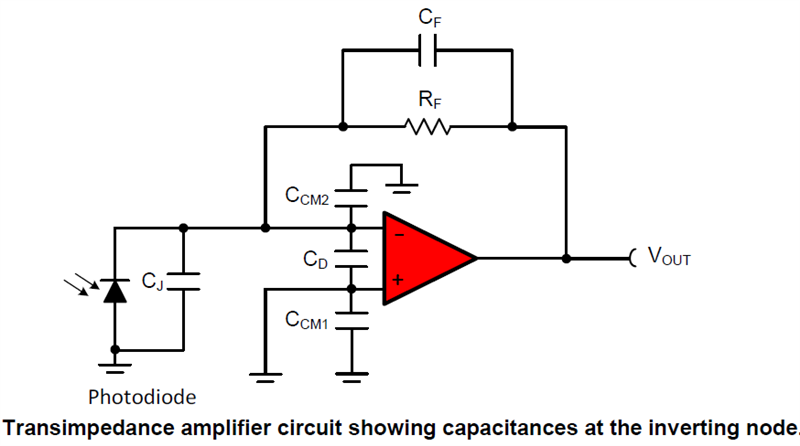
    Please follow procedure outlined by Kai to isolate the source of the instability.  In case the TIA itself is the cause, please provide schematic including details of value of junction capacitance, Cj, feedback cap, CF, and RF, which are critical to assure stable operation - for reference please see schematic of TIA below.

    Also, you may want to review the procedure for designing TIA shown in attached presentation.  

    7043.Op Amp Bandwidth for Transimpedance Amplifiers.pdf

    Additionally, there is an online training material covering the topic of TIA stability - see following link:  https://training.ti.com/ti-precision-labs-op-amps-stability-introduction

  • Hi Texas,

    The above suggestions mentioned in the chat have helped me a lot to overcome the said problems. Now, we want to design a TIA circuit topology where high variable current levels (50uA - 5mA) can be measured with pA (maximum 1 nA) resolution ie if the variable current at a specific time is 1 mA (feedback gain =250 ohm) and at very next time instant 1 nA current is added to inverting terminal of TIA which is making the total current to (1mA+1nA). Standard TIA topology (mentioned in the above chat) gives Vout = 250*(1mA+1nA)= 250 mV + 250 nV, measuring the change in Vout with 250 nA due to 1nA (250 nV here) is not feasible even with very high-resolution ADC (24 bit) on PCB. Can we efficiently measure the low current (1nA, generated due to device physics) which is overriding the high-level current (mA)? Please correct the following approaches (probably all are unconventional) to address the mentioned issue:

    1. Designing of two-stage amplifier where 1st stage TIA , and the second stage would have feedback integrator in gain, will it not help in measuring the difference signal?
    2. Placing a differentiator at inverting node of TIA?
    3. Can we embed a log amplifier with TIA to attack this problem?

    Detailed suggestions will benefit an analog beginner like me.

    Thanks and Regards,

    Deepak

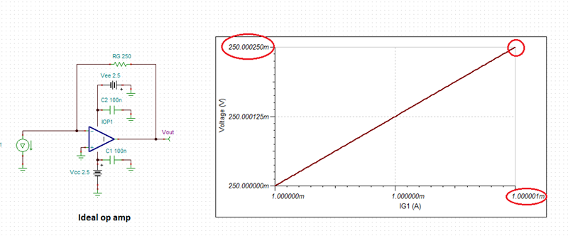
  • There is no easy way to measure 1nA change with 250ohm TIA as this implies 250nV resolution - see below.

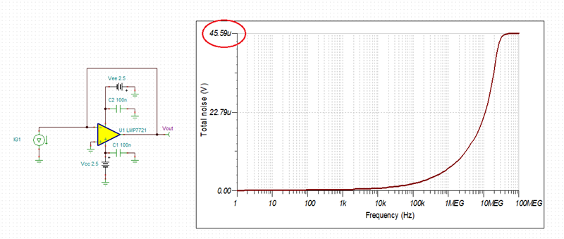
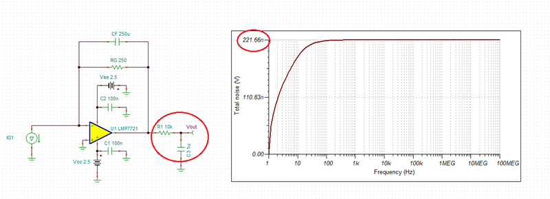
    Changing the input current by 1nA from 1mA to 1.000,001mA would require resolution way below the input voltage noise of LMP7721. Simulating the input noise in the best-case follower configuration shows total noise of 45.6uV - thus almost 200 times higher than required 250nV resolution.

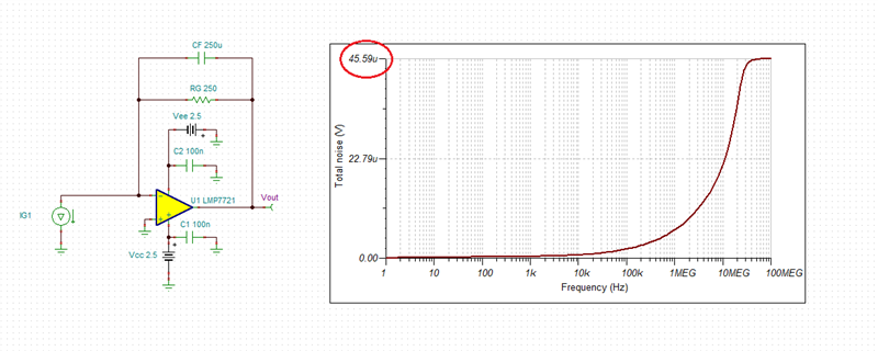
    Simulating the total noise in the actual application shows the same magnitude of 45.6uV - see below.  

    Thus, in order to lower the noise down to required resolution one would need to add a low-pass filter at the output and use multi-sample averaging - see below.

    Since you do not attempt to measure sub-pA currents, there is no need for LMP7721 with max IB of 20fA - instead you could use OPA328.

    Please see examples of TIA implementation under following link: https://www.ti.com/lit/an/sboa558/sboa558.pdf

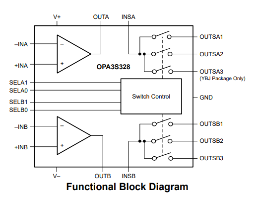
    Even better would be to use OPA3S328 that includes OPA328 together with three internal low-leakage switches for gain changing - see below.

  • Deepak,

    I'm going to close this thread since we have two separate threads running for the same topic.  Please post on the other thread for further questions.

    Regards,
    Mike