This thread has been locked.
If you have a related question, please click the "Ask a related question" button in the top right corner. The newly created question will be automatically linked to this question.
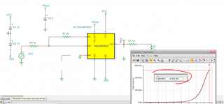
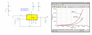
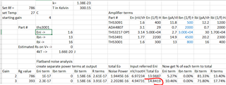
Hi there, this is the same issue I've been having with the THS3491 as well, they look great in simulation then get a TI evaluation board on the bench and the noise levels are much worst in reality. This time I have a THS3001 inverting configuration on a TI THS3001EVM with 1k input, 2k Rfb.with non inverting input grounded. The simulation shows 129uV RMS noise in a 150MHZ bandwidth, my scope noise floor is 75uV RMS so the maximum I should be seeing is 167uV on my TEK scope. What I actually see is 330uV RMS ie double the noise the simulation predicts ! Further to get the simulation to match bench result I have to put a 15k resistor between in+ and ground which is crazy. Can you please comment about TI's noise modelling methods used for this part and if possible supply either a correct noise model or suggest the best workaround ? Thanks, Steve
Well Steve, on a slightly different issue,
At one time I was part of a decision to put NRND on the THS3001 web page instead of fixing a known design probably. Not there any more, so I am curious if they fixed it (would require a new mask set, quite expensive) or just decided to continue to take chances with production variations?
Hi Michael, So does TI have any actual support people who can answer these questions, or do they rely on good folk like you to help them out? Clearly there are some issues with the THS3001 and 3491 noise models to be addressed. I don't mind if TI provides a better noise model or give me what I need to hack the model or add external parts to make it work but I have a fortune 500 client that need a simulation model that reflects reality for more than just one gain/resistor value combo. By the way this is why I prefer Analog Devices where possible because at least there I can pick up the phone and talk to a real apps guy and issues solved rather than posting on the TI forum and get "ghosted".
There are real people at TI as well. But for the 1999 THS3001 there is likely no one originally involved with that development.
It is kind of unlikely the THS3491 noise model is faulty. It is almost 100% sure the THS3001 model is defective. There is also a much looser match from paper to product on the THS3001. Personally, unless they have fixed that internal design problem I would ignore that device. Perhaps your client would like to fund that fix? Internally, I would guess a budget in the $250k region for masks and manpower. And I actually did do a businees plan at one time to fix this, but the problem is always you are displacing engineering time from allegedly more rewarding activities.
Full schematic on how you are testing or simulating the THS3491 would be useful - just words are hard to deal with while a picture tells a better story, Kai and I can handle .asc files.
I did cover some of these noise and noise modeling issues in a series of AudioXpress artilces, here is that litsing,
Hi Michael, so what is the effect of the THS3001 internal design problem ? I ask because assuming datasheets are correct the THS3001 current noise is 16pA/RtHz but the THS3491 is 20pA/RtHz.. Also THS3491 has wider bandwidth which adds noise because I need to series terminate making filtering tricky. Circuit whichever part I use is the same a simple x2 inverting amplifier with Rfb =2k, Rin = 1k. As for the THS3491 being a good match my simulation using TI model predicts 438uV noise but on the bench having backed out the scope (150uV) noise the THS3491 noise is 526uV.so 20% higher. As TI doesn't have an easy way of uploading files I will email the ASC file to you directly. Cheers, Steve
So to upload .asc files here, you have to zip them first,
That 2k ohm feedback is of course bandlimiting a bit an adding noise,
Your file shows the 2018 netlist, you know there is a 2020 updated version online now.
So you are reporting integrated noise numbers - through what brickwall bandwidth?
Ok, working in TINA with the same THS3491RGT model, is this about what you have?
In simulation you can brick wall your noise itegration pretty easily, your .asc file showed 0.1Hz to 150MHz,
Here is that TINA sim of output integrated noise - this 438uVrms - this matches exactly your LTSpice number. Now, when you look at your 526uVrms measured number how are you brick wall bandlimiting at 150Mhz? Likely you are just integrating a little more noise physically here.
So here I went further out in noise integration, takes quite a bit to hit 526uVrms - 400Mhz on this output noise profile.
One really quick way to integrate more noise is have a peaked frequency response, here I added 2pF on output and inverting summing nodes, almost imperceptible change in AC response, but now we hit 526uVrms all the way down to an implied integration span to 300MHz.
It doesn't take much, extend the output noise span with just a little bit of peaking.
Hi Michael,
I'm only using 150MHz span and whether it's 384/768 or 1k/2k the addition of 2pF capacitance makes minimal effect in the simulation. Also increasing the bandwidth from 150MHz to 300MHz would inherently increase the noise by sqrt (2) ie 1.414 so assuming a uniform noise distributionand excluding the 2pF capacitor I'd still expect to see the noise increase from 438uV to 438 *1.414 = 619uV so not convinced
Do you know much about the THS3491simulation model ? Assuming it's just behavioral are you confident that it actually models bandwidth roll-off for different Rfb values ? Also current noise me not being an IC designer but is this a constant does this parameter change with RfB/gain ? If it does is this included in the model ? Guess where I'm going with this is I suspect the part was characterized under just one set of conditions and used to produce the model. So the more divergent we are in use case from the conditions used the bigger will be the simulation errors. Not so much a bad model but more lacking the finesse for the varying use cases.. Am I right or are you saying the parameters are more or less constant, or that the interactions were accurately modeled to cover a variety of use cases ? If the answer is no then the only solution would be to test on the bench and build/modify the model.
Hopefully you will know these answers ?
Best,
Steve
Have you measured your reponse shape in the intended configuration.
The models are very very good. Input referred noise models are intended to track across all external conditions - your changing resistor is also changing the output response shape. When you say 150MHz BW, often we need to adjust that for noise power BW.
I will do a few more sims here, I was having trouble with the 2018 model giving the correct spot noise at the output, but the earlier 2016 one worked well,
So here I am just running you 2 sets of R values, the 768 feedback is much lower noise due to the inverting current and R noise terms, it is broader band though so if your 150MHz is not actually a brick wall filter, might integrate quite a lot more noise,
Here are the 2 SSBW response curves, you can see the lower Rf is quite a lot broader band,
And then the integrated noise to 150MHz hard stop, the gain of -2 with Rf = 768 should be a lot lower integrated noise,
Hi Michael,
So to recap you're pretty confident that the THS3491 model is accurate enough noise and bandwidth-wise to reflect changes in Rf but the THS3001 model is way too optimistic right?
Even so from bench measurements swapping between THS3491/3001 or comparing evaluation boards with 1k Rin and 2k Rfb I do get better bench noise results using the THS3001. So understanding the model limitations my question what is the design floor that might make me not want to use the THS3001 ? Also is there anything I could do to fix the simulation issue ie external parts etc ?
Second I've solved the THS3491 differences, simulation and evaluation board now seem to agree (may have been a noisy bench power supply) However for my application I need to drive the positive and negative supply rails each from a THS3491 (Don't ask why it's confidential). My question is there any way I could decouple the supply pins to the amplifier THS3491 without causing instability to the supply 3491's or increased noise on the amplifier stage ? I notice that if I only decouple the power supply 3491's then the amplifier noise increases by some 100uV.
Best, Steve
So yes Steve, the THS3001 does have a lower noise according to the datasheet. Here I added that to the prior example in the calculation spreadsheet and for those conditions it went down from 18nV to 15nV. There are threads here in e2e on adding external noise generator to increase the model noise. I also believe you had a prior discussion on supply bootstrapping here. You should perhaps close this thread and open a new one on supply bootstrapping hopefully with that same earlier internal TI person.