This thread has been locked.
If you have a related question, please click the "Ask a related question" button in the top right corner. The newly created question will be automatically linked to this question.
Hello
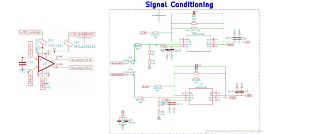
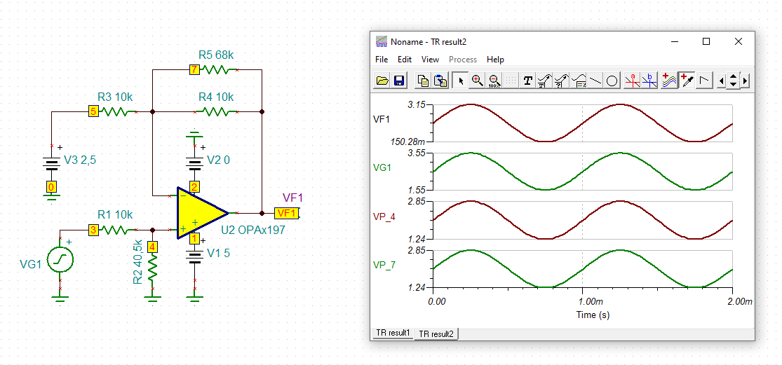
I wonder if OPA197 / OPA4197 can work on single supply ? I have always been using them in dual supply configuration. Logically they should work fine and In the data sheet it's stated that they can work in single supply operation but for some reason when I Run simple simulation in PSPICE for ti , the simulation takes a lot of time and sometimes fail.
Thank you very much in advance.
BR
Amr Wael
Hi Amr,
Yes, the OPA197/OPA4197 can work with a single supply. Just need to be aware how the op amp's input common-mode voltage range (Vcm) and its output voltage (Vo) become referenced to a single supply's mid-supply point as opposed to a dual-supply ground.
There is an older Burr-Brown Applications Bulletin that should be of some help explaining how op amps can be applied using a single supply:
https://www.ti.com/lit/an/sboa059/sboa059.pdf
The OPA197/OPA4197 simulation model should function correctly. Do provide us with your simulation circuit schematic as Kai stated so that we can look for any problem it might have.
Regards, Thomas
Precision Amplifiers Applications Engineering
Hi Thomas ,
Thank you for your reply.
My input to the opamp is actually the output of AMC1200 , which is a 2V p-p signal that oscillates around 2.55V (2.55V offset)
I am using OPA197 in a fully differential amplifier configuration with 4 resistor to make the signal oscillate from 0.15 Volt to 3.15V (3 V p-p) that oscillates around 1.65V (1.65V offset) , Maybe the 150 mV is very close to the GND that's why the simulation fails ?
Do you suggest that under these conditions I could use it in dual supply configuration or is there another recommended operational amplifier similar to OPA197 that is going to work with a single supply using the same configuration and preferably P2P replacement.
Thank you very much in advance.
BR,
Amr Wael
Hi Kai ,
Here is a little bit of the schematic , I illustrated below the ranges of my signals
Hi Amr,
it can often be seen that SPice models which run properly with a bipolar supply voltage do not properly run with a single supply voltage and vice versa. And it often plays a role which simulator you use.
For me the simulation runs properly in TINA-TI:
While it is true that the common mode input voltage range is not violated, your input signal runs through the critical transition region where both CMOS-FETs input pairs are on. See figure 8 and section 7.3.6 of datasheet. This can make problems in certain simulations and with certain simulators.
Another issue is the output voltage. According to the "open-loop voltage gain" specification on page 9 of datasheet, your output signal comes the supply rails so close that the output stage begins to leave the linear operating range, just as you already mentioned. This also can make issues in certain simulations and with certain simulators.
By the way, when you increase the input voltage more and more, even the above TINA-TI simulation gets convergence problems at some point and stops working properly.
There is a group of OPAmps which do not show this transition region, like the OPA325 for instance. Search for a zero-crossover device. Or stay with the input and output voltages farer away from the supply rails.
Kai
Is this issue just related to the simulator or am I going to face similar practical problems in real-life circuits ?
Hi Amr,
section 7.3.6 says:
"There is a small transition region, typically (V+) –3 V to (V+) – 1.5 V in which both input pairs are on. This transition region can vary modestly with process variation, and within this region PSRR, CMRR, offset voltage, offset drift, noise and THD performance may be degraded compared to operation outside this region."
I personally would not operate the input stage in this transition region, if highest precision is wished.
Kai