This thread has been locked.

If you have a related question, please click the "Ask a related question" button in the top right corner. The newly created question will be automatically linked to this question.

OPA549-HIREL: OPA549-HIREL for ultrasonic transducer

Part Number: OPA549-HIREL
Other Parts Discussed in Thread: OPA549, TPA3255, OPA462, OPA541

Hello every one 

Happy new year ; 

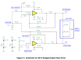
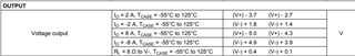
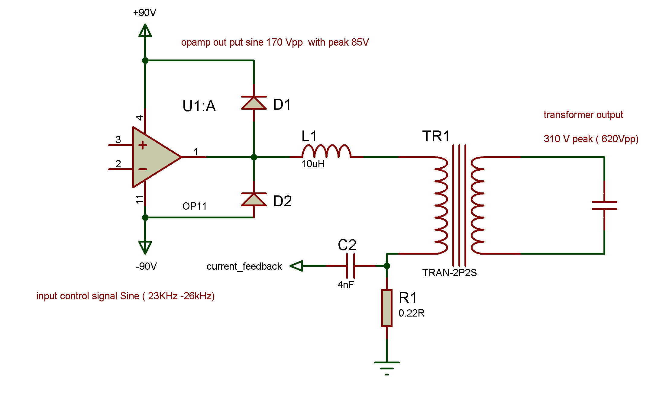
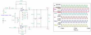
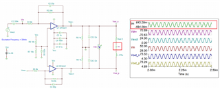
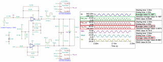
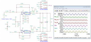
I am desiging an ultrasonic driver wth impedance tracking ; I need to drive the  trancducer with sine wave about 30kHZ  with Vpeak of 350V  about 100W.  so I am  planing to use OPA549 with +/- 30 supply  then a stup up transformer   1:14  . Could anyonw guide me if OPA549  is suitable for ulrtasonic ? and how to calculate the high frequancy transformer  to match the trancducer. 

Also I am think ing to use  TPA3255 with transfomer  1:7 ; with power   50V. 

Anyone could help me and I  would be thankful 

Regards 

Hector 

  • Hi Kai, 

    Thanks for answering inquiries while we are off. Happy New Year!

    Hi Hector, 

    Could anyonw guide me if OPA549  is suitable for ulrtasonic ?

    OPA549 power amplifiers that replacing OPA462 should work for the application, see the attached application note. 

    https://www.ti.com/lit/an/sboa502/sboa502.pdf?ts=1672791912411&ref_url=https%253A%252F%252Fwww.google.com%252F

    The transformer's turns ratio is 1:14, which means that the primary side of transformer need to drive up to 350Vpk/14 = 25Vpk (700Vpp on the secondary side), The ultrasonic transducer consumes approx. 100W, and each OPA549 needs to drive up to 50W (assumed avg. power in sinusoidal waveform at 30kHz) for the application.

    With +/- 30V supply rails, it is likely that OPA549 should have headroom  for the peak voltage, but I need to simulate it for certain (the headroom may be close; we may consider to use asymmetrical power rails, if the transducer is floating.). Please provide us the transformer's LCR parameters for an accurate simulation. 

    My guess is that your ultrasonic transducer is driving is floating configuration at the transformer's primary & secondary sides. In fact, I believe that your application may be similar to an resolver driving configuration, as presented in the link below (except that OPA549 will source/sink the required current to drive the ultrasonic transducer).  

    https://e2e.ti.com/blogs_/b/analogwire/posts/how-to-boost-the-performance-of-your-resolver-without-compromise

    and how to calculate the high frequancy transformer  to match the trancducer. 

    Since the transformer is operating at 30kHz range (likely in sine waveform), you need to pick a transformer that can operate at 30kHz with a minimum magnetic core loss. Do you have transducer's impedance parameters? In addition to minimum core loss in the transformer, the secondary's transformer needs to have lower impedance to be able to drive the transducer. Please let us know more design requirements for the project. 

    Best,

    Raymond

  • A Happy New Year to you too, dear Raymond Relaxed

  • Hi Hector,

    according to my links, I would ask manufacturers of inductances and coils for a suited transformer solution. I'm sure that they can offer you a suited transformer and can tell you how to drive it. And they should be able to provide an equivalent circuit model of their transformer.

    Kai

  • Thank you for your help ; 

    here is the sketch of my driver which is built years ago; here we use OP04 from APex analog which is an expensive device and we need to change it. 

    the output of the OP04 gives a 170Vpp to drive a transformer of the primary inductance of about 1.1mH and the secondary is about 14.25mH so the ratio is 3.6. 

    we can have about 310V peak on the transducer 620Vpp which is about 80Watt  ultrasonic power. 

    for the new design, we think to use OPA549 which can output  50Vpp; we can't change the inductance of the secondary because it matches the transducer for maximum power, so its 14.25mH; what we need now change the ratio of the transformer to get the same peak 310v peak. so that the new ratio is  620/50= 12,4. so that the primary inductance now is 92uH. 

    1. my questions:  in the case of floated output ( no transducer is connected )  the output current is about 1.7A peak which means about 30 watts without load!  AM I right here? 

     to reduce the current we need to higher the voltage to reduce the transformer ratio to get higher inductance on the primary;  thinking to use two OPA549 in a differential configuration to get a 100 vpp; is it possible?  so the output current can be less to 0,8A .

    Any other suggestions please to solve this issue ? Thank you in advanced 

    the information of the transducer is attached it has Cp = 3000 pF ; 2032 Specification (9).pdf

    Regards 

    Hector 

  • Hi Hector, 

    my questions:  in the case of floated output ( no transducer is connected )  the output current is about 1.7A peak which means about 30 watts without load!  AM I right here? 

    If the ultrasonic transducer consumes approx. 80Watts, say this is the average power, then the primary side of driver has to delivery approx.  80 watts total as well (average). with a floating configuration, each op amp shall deliver approx. 40 watts/each (assuming it is 100% magnetic coupling). Yes, 30 watts per op amp is in the ballpark, if we are able to perform the power factor correction on the transformer's primary side.

    thinking to use two OPA549 in a differential configuration to get a 100 vpp; is it possible?

    It may be doable with a differential drive configuration (with floating transformer and load),  but I have to verify it with the simulation tomorrow.

    You have two design options. Option 1 is using the technique mentioned above. 

    The 2nd option: Use single OPA462 + current buffer output or current boost amplifier to drive the transformer/transducer, which the design is similar to APEX AP04 PA configuration (without the high cost of PA04 PA).

    Please let us know which method you are going to adapt in the design. 

    Best,

    Raymond 

  • what about considering the OPA541 device ? it has higher voltage supply; 80v .

  • Hi Hector, 

    There are two driving options for the ultrasonic transducer, please let me know which one you are interested in. 

    1. OPA549/OPA541 to drive the primary side of the transformer in floating configuration. You are looking for 50Vpp voltage swing, approx. 80W (avg power) total at the primary side of transformer driver. 

    2. Use OPA462 + complementary BJT or MOSFET current booster to drive the transformer, which is similar to your previous design configuration. 

    The overall cost may be comparable, option 2 may be slightly lower in cost. 

    BTW, what is ESL in the 1mH primary side of transformer? 

    Best,

    Raymond

  • Hi Raymond ; 

    we will use the flaoting one as in my schematic above ; but i think we can go with 80Vpp now if we can use OPA541. 

    Regards 

    Sami 

  • Hi Hector, 

    Enclosed is an example of floating drive at the driving transformer. Since you did not provide me with the ESL figure, I estimated one for the simulation, and I have not include all the protective elements at the driver side. In addition, the driving input is altered from 50Vpp to 80Vpp. So please consider that this is a suggested driving example for the HV application. 

    Enclosed is the Tina simulation per the example. 

    OPA541 32kHz Transformer 01062023.TSC

    If you have additional questions, please let us know. 

    Best,

    Raymond

  • Hi Raymond ; 

    thank you for the great work you have done for me .  for the transformer the ration should be 1:5; 70 vpeak to  350peak for the trasnsducer ; 

    the secondary inductance should be fix 14.25mH to match the transducer so ; we can have now primary inductance of 570uH . 

    my second question in your simulation ; that the primary side will draw minimum 380mA even if no load ; right?  

      How  could we calculate the avarge power now in each opamp to find the suitable supply ; if we assume 100watt  maximum power ; in the primary side . Does that mean each opamp will share 50watt? 

     what about the  heat sink  for opamps now ? 

    in my previous shematics we measure the current using a low side resistor ; now i think we need high side configuration  tomeasure the current in the primary side , right ? any suggestion here please ? 

    Thank you again 

    Best Regards 

    Hector 

  • Hi Hector, 

    that the primary side will draw minimum 380mA even if no load ; right?  

    I changed the primary inductance to 570uH and the minimum current without the ultrasonic transducer's load will be approx. ±600mApk. 

      How  could we calculate the avarge power now in each opamp to find the suitable supply ;

    If ultrasonic is disconnected, the power dissipation while driving the transformer alone is approx. 29W. 15.2W will be dissipated from the upper OPA541 and 13.7W will be dissipated o the lower power amplifier. 

    OPA541 32kHz Transformer 01092023.TSC

    The slide below is shown how the power dissipation meter should be connected via Tina. Please keep in mind, the simulation assumed that ESL is 2Ω, since I do not have the actual transformer figures. 

    Does that mean each opamp will share 50watt? 

    In the ballpark, this is correct. 

    The impedance on the transformer's secondary is reflected back to the primary as Zp_reflect = Z_s*(Np/Ns)^2.  

    Lp = 570uH, Ls=14mH 

    Lp/Ls = Zp/Zs = (Np/Ns)^2  --> Np/Ns = 0.202, which is approx 1:5 in turns ratios. It depends on what Zs is in the ultransonic transducer, which determines how much power OPA541 will be dissipated. 

    If you are using laminated Si steel core for the transformer (flux density of ∼14000 gauss), it should be able to handle 32kHz without a significant core loss. There are two types of losses in the transformer design (my guess is that you want to build your own magnetic transformer), namely eddy current and copper losses. You should be able to achieve approx. 95% efficiency in the design, but the design is driven by losses vs. physical_size of the transformer size. The lower the losses, the larger the transformer core is going to be. Maybe you can tell me how large is your existing transformer that is used to drive the ultrasonic transducer.

    now i think we need high side configuration  tomeasure the current in the primary side , right ?


    In terms of current sensors, you can insert sensing resistors within the OPA541's feedback loop (see location marked by blue boxes), use instrumentation amplifier or current monitor to obtain the current information. 

    The thermal metric table is captured below. Since I do not have information about Tamb operating conditions, I am not going to comment on the topic. The application will require large heat sink, airflow to remove the heat generated by OPA541s, and prefer to operate near room temperature.  

    If you have additional questions, please let me know. 

    Best,

    Raymond

  • Hi Hector, 

    Please let me know that the power simulation is helpful. If you want to use OPA541, please make sure that the power amplifier will operate under the recommended Safe Operating Area (SOA), see the section below. 

    If your application is able to cool OPA541s effectively with large heat sinks/air flow or cooling plate etc., you should be able to make this working (lab or room temperature operating conditions and application). If this is automotive application, I am not certain if you are able to cool the OPA541s effectively. 

    Since you did not provide me with the actual transformer parameters, the above example is to simulate how to drive a transformer and estimate power dissipation on the drivers etc.. 

    In the previous reply, I mentioned about Power Factor Correction. When driving L, R, C loads, it involves Real, Reactive and Apparent powers. If you are able to reduce the reactive power in the complex load (to make the transformer/transducer behaves more as "resistive" load), you may further reduce power dissipation in OPA541s. 

    Best,

    Raymond

  • Hi Hector, 

    I am going to close this inquiry. If you have additional questions, please let us know. 

    Best,

    Raymond

  • Thank you Raymond ; 

    I am sorry I was out of the office ; soon we will do the tests and I will inform you with results ; for now thank you very much for your great support . 

  • Hi Hector, 

    Ok, please let us know if you have the testing results. I am going to close this inquiry for now. 

    Best,

    Raymond