This thread has been locked.

If you have a related question, please click the "Ask a related question" button in the top right corner. The newly created question will be automatically linked to this question.

OPA4171: OPA4171-Q1 Application issues

Part Number: OPA4171

Hi expert,

I have a question about OPA4171 application; what is the impact when IN+ exceeds the power supply? How should the input current be evaluated? 

When IN+ exceeds the power supply voltage of 5V, the op amp will clamp the IN+ voltage at 5.5V. How to ensure that the op amp will not exceed the SPEC of the maximum input current?

Looking forward to your reply, thanks..

  • Hey Hangjie,

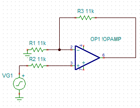
    The way you limit this current is with a series resistor between what is generating your voltage and your input pin. For example, if your input is shorted to a 16V battery, you would need to limit the current to less than 10mA over an almost 11v drop. Solving for the necessary resistor for 11V/10mA = 1.1k. I would add some headroom and make your input resistance 11k if your design allows for it.

    The series resistance would be placed as shown below. 

    Best,
    Jerry

  • Hi Jerry,

    Thanks  for your reply, it's clear for me. another question:

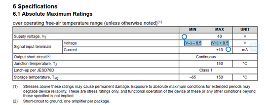
    When the VGC voltage exceeds the power supply voltage, will IN+ be damaged because it exceeds the MAX value?

  • Hi Hangjie,

    this specification has to do with the internal input "protection diodes" from the inputs of OPAmp to its supply voltage pins. And the idea is to limit the current through these "protection diodes". It is assumed that a voltage drop of up to 0.5V across the "protection diodes" does not cause a destroying current through them. But if the voltage drop can exceed 0.5V, then a current limiting to below 10mA must be provided. And it doesn't matter, if the voltage drop rises above 0.5V, if the current is limited to below 10mA at the same time. It's the current through "the protection diodes" what counts not the voltage drop across them, if once the current is limited.

    Keep in mind, that the "protection diodes" need not to be true diodes. It's more a sophisticated protection circuit (read "ESD cell") which contains at least one pn-junction. (That's why I have enclosed the phrase "protection diodes" in quotation marks.) And the protection circuit may differ from OPAmp type to OPAmp type.

    Also keep in mind that pn-junctions show a strong temperature behaviour. So, if you measure the current through the "protection diodes" at room temperature you may find a current way below 10mA even if you increase the voltage drop across the protection diodes beyond 0.5V. But this heavily changes when you increase the die temperature to the allowed maximum junction temperature. Then you will definitely need the current limiting Relaxed

    Kai