This thread has been locked.

If you have a related question, please click the "Ask a related question" button in the top right corner. The newly created question will be automatically linked to this question.

LM358: Output not toggling in Schmitt trigger

Part Number: LM358
Other Parts Discussed in Thread: LM393,

Hi, 

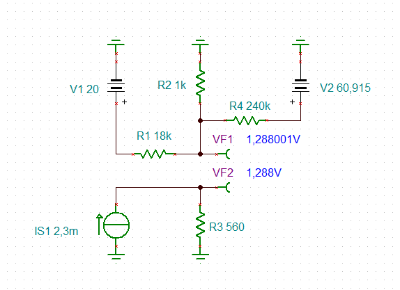
I am designing a schmitt-triger circuit as shown below to toggle the output when input crosses a threshold voltage. The opamp is operating at 20V supply. 

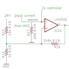
The threshold voltage is set to 1.125V as measured by Voltmeter on non-inverting pin. On the inverting pin there is a resistor which is connected to a current source and other end is ground. So opamp has to measure voltage accross it. Since Threshold is 1.125V the corresponding current is 2.01mA. But when actually fabricated its PCB, it was found that the output is toggling at 2.3mA which is much farther from threshold. 

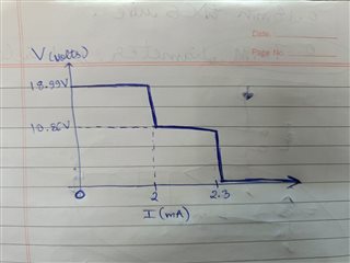
The output voltage vs input current accross R17 is as follows. 

18.77V at 2mA accross R17, 10.85V at 2mA-2.2mA range accross R17,  0.011V beyond 2.3mA. 

The strange thing is that I have another circuit with same components that is toggling as expected but this one is not. What could go wrong. 

Is there is anything I am missing in datasheet? 

  • Hi Swapniil,

    the LM358 and the LM393 are not the same. The first is an OPAmp (with a push-pull output stage) while the second is a comparator (with an open collector output needing an additional pull up resistor).

    So, what are you using?

    Kai

  • Hi, 

    Don't go by schematic, I made this as LM393 file was available at that time in CAD software. On real hardware I have used LM358

    Thanks

  • Swapnil,

    Check the output low and output high voltages. Did you use these values in the hysteresis equations?

  • Hi Swapniil,

    to make the LM358 toggle at an input current of 2.3mA, the LM358 would have to output about 61V:

    This is impossible of course, when being powered by a 20V supply voltage. So, either there's something wrong with the components arround the LM358 (component values, wiring, etc.) or the LM358 is damaged.

    I would measure the voltage drop across the 560R resistor when a current of 2.3mA is flowing: If it still is 1.125V, then the input stage of LM358 is damaged and allows a faulty high input current to flow into the LM358. This usually happens, if the input voltage once exceeded the absolute maximum ratings, or by other words, if the LM358 has seen a destroying negative input voltage of less than -0.3V. According to section 8.3.3 of datasheet the input current should be limitied to <1mA in this case, best by the help of a suited current limiting resistor between the 560R resistor and the -input of OPAmp.

    18.77V at 2mA accross R17, 10.85V at 2mA-2.2mA range accross R17,  0.011V beyond 2.3mA. 

    This is another indication that something is wrong with the LM358: The threshold region is way too flat and not steep enough. So, I guess the LM358 is damaged.

    Kai

  • Hi, 

    I changed the IC LM358 with a new one and still getting the same response. 

    Voltage accross 560R is 1.320V when ~2.3mA flowing. So the voltage part is correct. At this point the voltage at pin3 of opamp is  1.105V (which is somewhere between 1.13V and 1.063V two thresholds in which it is supposed to operate as schmitt trigger)

    The problem is about not having a sharp transition from Vcc to gnd in output. The output stays in middle for some input voltage near threshold and then drops to 0 which should NOT happen. 

  • In reference to previous message I am attaching a rough diagram of output voltage of opamp wrt to Current accross 560R for LM358 opamp. 
    (Pls note the graph is not to scale, only refer the values and graph behavior) 

  • Another finding wrt to this is: 

    After the scmitt trigger there is a voltage buffer and a voltage divider which is going to an AND gate. When I cut connection of AND gate, the circuit started behaving perfectly as it should be. 

    How can an AND gate hinder its performance as it is CMOS based gate. Also using this is quite necessary so can you suggest a way to use it? 

  • Swapnil,

    It looks like the output loops back to the input creating a closed loop that holds output stable (after 2mA) until current gets to 2.3mA and that breaks the closed loop.

    You have a line call "To controller" ; does pin 1 out of op amp also go to this "controller"

    What I suspect it that controller is adding (or subtracting) current from pin 2 node. Can you draw out pin 2 voltage vs I(ma) too. 

    Can I assume that 20V is constant and so is pin 3 voltage?

  • Hi Swapniil,

    a complete schematic would be helpful.

    Kai

  • Hi kai, 

    I identified the whole problem case, but I am unable tor reason it.

    I have only have a opamp based voltage-buffer and a voltage divider(56k and 10k) after this Schmitt trigger which connects the output voltage to low voltage microcontroller. 

    I noticed that after the voltage divider is converting the 20V logic level to 0-3V logic and I am sending it to controller. Till then everything was working perfectly. 

    This above stated problem started when I connected an AND gate parallelly with that signal. I measured current going in AND gate input, it was very less than 1uA. When I attached a 10Meg Ohm resistor on input pin of AND gate and connected to voltage divider. Then the circuit worked well. 

    Since the measured current was very less how can 10Meg Ohm made the circuit work. I initially thought it was due to loading effect of voltage buffer, but seems like it is not. 

    I am totally confused with this problem statement. If you could help me it would be better. 

  • Please show a complete schematic.

    Also, what happens when you disconnect the microcontroller from pin 2 of LM358?

    Kai