This thread has been locked.

If you have a related question, please click the "Ask a related question" button in the top right corner. The newly created question will be automatically linked to this question.

BUF634: Glitch in the output of BUF634P

Part Number: BUF634

Dear Team,

I am using BUF634 for my application.For testing I made a proto board(Hand soldering).Board is given below.
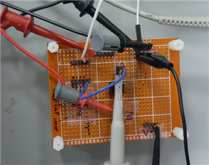
I am proving a supply of +15V and -15V and decap of 10uF is provided.

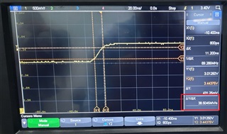
My input is a square waveform with a DC offset and a frequency of 33Khz.Please see the I/P pic below.

At the ouput of the Buffer a 10pF capacitor is connected.When I observed the waveform at the output I can see glitching at the both rising and falling edge.

May I know why it is occuring.

Please see the images below.

Regards

HARI

  • Probably hitting a slew limit, try low pass filtering your input signal to slow its edge rate down, 

  • Hi Michael,

    My signal is 33Khz and I set the BW to 180Mhz(30 MHz to 180 MHz).

    May I know how slew issue is occuring here.

    Regards

    HARI

  • Zoom in on your input signal and find the dV/dT for it and compare to the BUF634 SR. Also, you really should be using the EVM board to get lower parasitics on your supply lines, Hand wiring a part this fast is kind of asking for trouble. 

  • okay,will check it.

  • Hello Hari,

    For new designs, it is recommended to use the BUF634A, a drop-in replacement part with upgraded functionality.

    Please let us know when you are able to investigate Michael's recommendations.  Also, I can help you order an EVM if you require assistance.

    Best,

    Alec

  • Hi Team,

    I measured the slew rate of my source(TEKTRONIX FUNCTION Gen).Please see below

    it is coming 38MV/s.

    if I convert I will get 38V/uS(Please confirm).

    Regards

    HARI

  • Hi Hari,

    don't feel offended, but it's impossible to carry out representative measurements with the BUF634 sitting on a simple bread board. A solid ground plane is a must when handling this ultra-fast 2000V/µs buffer.

    Another issue is cable termination. You must provide proper cable termination at the input and output of BUF634. And the BUF634 must sit closest to the input and output connectors. If not, you may additionally need to provide microstrip or stripline technique between the connectors and the BUF634. Simple centimeter long wires as your setup shows will not do the trick and may give totally weird results.

    Kai

  • Hi Kai,

    Your suggestions are always valuable for a novice like me.I will never offended.

    May I know what you mean by cable termination.

    Do I need to keep 50 ohm series resistor at the input of the buffer.

    Michael told me to measure the slew rate of the input source(Function Generator).I put it in the post may I know is it correct

    Regards

    HARI

  • Hello Hari,

    Working with the BUF634(A) is going to require learning about high speed layout techniques and terminology.  As a starting point, there is this TI document on high speed layout.  Termination refers to the characteristic impedance of the traces and the impedances present at the buffer inputs and any connectors/connected circuitry.  Section 1.3.2 is a good start for learning about termination, in the linked document. 

    Terminating the input of the BUF634(A) into a poorly-selected or fluctuating impedance will result in poor behavior.  Most TI product datasheets include descriptions of the electrical characteristics, as well as graphs with various impact of the available choices.  Many datasheets contain a short but relevant layout section as well. 

    While it is quick for obtaining a result, the results from a perf-board/proto-board setup for a high speed buffer will be incorrect, weird, and/or misleading.  I recommend either the use of the BUF634AEVM for buffer evaluation, or the use of high speed layout principles on a PCB.  If you are not as familiar with designing PCBs or designing for high speed devices, there are other strong resources available online from PCB vendors & educational sources.  

    If you decide you would like to utilize an EVM, please send me a private message and I can assist you with that operation.

    Otherwise, please be patient with yourself and your design, as high speed layout and PCB design is not a 'learn it in one day' craft.  Kai & Michael have strong experience in this area, but you may find you need to do learning offline from the forum.  We are here to help, but sometimes we assign homework or readings Slight smile.

    Best,

    Alec

  • Hi Alec,

    Regarding EVM ,I will check with my management and let you know.

    My office is located in India.Hope that won't an issue.

    Regards

    HARI

  • Hello Hari,

    I await your response; I will confirm with my team on my recommendations.

    Best,

    Alec

  • Hi Hari,

    the connection between the output of signal generator (50R output !) and the input of BUF634 must look this way (only focus on R4, the 50Ohm cable and R19, because this picture is from another thread):

    The signal generator already contains R4, if it provides a 50R output. But you have to mount a 50R resistor from the input of BUF634 to signal ground (ground plane).

    The same is valid for the connection between the output of BUF634 and the input of scope. Here you need to add R4 to the output of BUF634. And you need to set the input impedance of the scope to 50R. The scope already contains R19 then.

    The BUF634 must sit on a solid ground plane with the decoupling caps being connected closest to this solid ground plane. The connectors' grounds and the grounds of 50R resistors must also connect to this solid ground plane. The connectors must sit closest to the 50R resistors and the 50R resistors must sit closest to the BUF634. Only then you have the chance to see the real behaviour of BUF634.

    Kai

  • Hi Kai,

    Thank you very much

    Regards

    HARi