This thread has been locked.
If you have a related question, please click the "Ask a related question" button in the top right corner. The newly created question will be automatically linked to this question.
Hi,
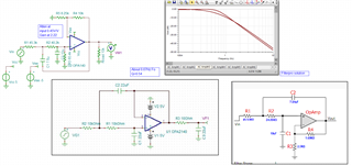
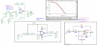
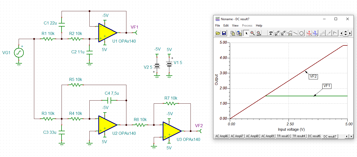
I'm designing a Sallen-Key filter and need to know the DC transfer function of the filter.
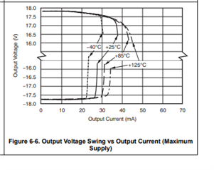
The OPA4140 touts Rail-to-rail output, so I don't understand why my DC sweep from 0-5V doesn't result in an output sweep of 0-5V.
If I bump the power supply rails to +/-8V, it works just the way I expected. I don't understand why a rail-to-rail output amp won't go rail-to-rail.
Thanks in advance.
Blake
Well RRout is a marketing term, all such devices require some headroom, the plot implies about 0.25V no load (this is on+/-18V supplies)
Hi Blake -
Agreed with Michael - you are limited by your common mode range. You won't be able to use this device if you want to keep the Sallen-Key architecture and 5V rails.
You could try an amplifier that has rail-to-rail performance but there will be other tradeoffs. The OPA140 is a very popular JFET input amplifier, If you can move the rails to 8 V, then that is the recommended approach.
Regards,
Mike
You could also do somethng like this, very approx pass here, pretty close but the updated design is a little higher Q and Fo, but you get the idea, attenuate at the V+ node to stay in ranges, showing the same source R as the unity gain SKF needs, and then add gain to the amplifier stage to get back to unity gain, Again this would need some work to exactly match original filter, but just an idea.
That's a good point. Noise will get impacted since the noise gain goes up, but, if noise isn't critical then the additional attenuation + gain should work.
Regards,
Mike
And actually, attenuating with the input resistor might be more tractable. Here I put a 0.6X atten in that R as a thevinin source still hitting the Filterpro 45k input R, and then moved the gain back down to 1.66X to recover that input atten, matches the original design much better,
I was pressed for time yesterday, what I had done was extract the existing design Fo, Q then put those back into Filterpro to adding that 1.66X to the design. This gave me a new set of RC to target in the filter to hit the same Fo, Q. And I was going to standard RC values without any kind of best fit algorithm. I have for the MFB but not the SKF 2nd order LP.
And yes, this not decreasing the output noise, The green curve is after the post RC I put back in, flattening out at about 0.6uVrms integrated output noise,
and this updated file,
Hi Blake,
sometimes I prefer the MFB low pass filter rather than the SK low pass filter:
Kai
Kai,
Thanks as always for the suggestion - very nice that you matched the response of MFB to the SK.
Blake, let us know if there's anything else we can help with here.
Regards,
Mike