A related question is a question created from another question. When the related question is created, it will be automatically linked to the original question.
If you have a related question, please click the "Ask a related question" button in the top right corner. The newly created question will be automatically linked to this question.
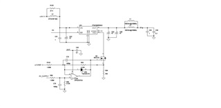
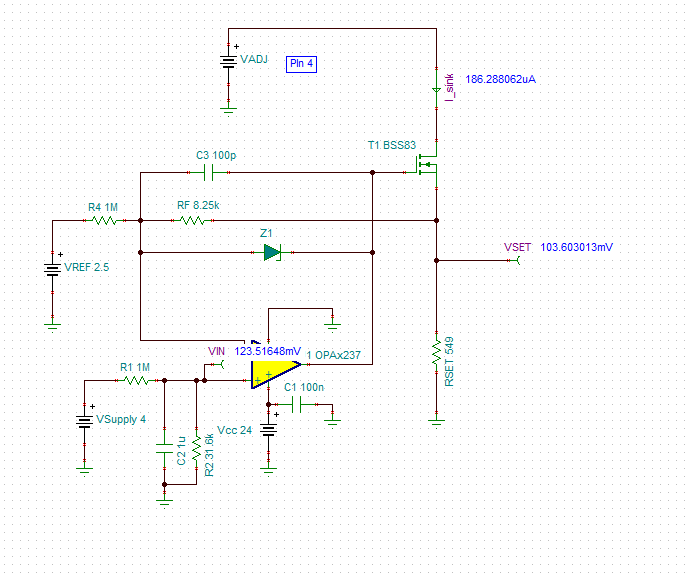
The OPA2237 and BSS123 FET form a DC current source. Assuming the negative supply (V-) of the OPA2237 is connected to GND, as connected with the 2.5V reference and 4V supply, the sink current is approximately is roughly, VSET / RSET = ~103mV / 549Ω = 186μA as shown on the simplified simulation below. The current source works as long as VADJ voltage (drain of the FET transistor) has a voltage above VSET.
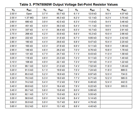
The PTN78060WAS datasheet recommends placing a resistor between Vo adjust control pin 4 and GND to adjust the output voltage; and explains the relation of the external resistor value against the expected output voltage on equation (1) and Table 3. However, the datasheet does not seem to provide information on how to calculate the VADJ current relation to output voltage.
I am part of the Precision Amplifiers team; hence, I will refer this question to the experts on the Power Management Applications team, since I do not have detailed information about the PTN78060WAS.
This configuration looks fine to me since what you are doing is adjusting the resistance seen by the VADJ pin. At first, it is open if MOSFET is not conducting, and then afterwards, output voltage will be modulated based on voltage applied at gate.
Attached is the simplified TINA-TI file. Please note, the circuit in the simulation uses a different FET device since I don't have immediately available a model for BSS123. Also, you will need to ensure the VADJ pin voltage is always above the VSET voltage for the current source to be in compliance. I have referred this question to the experts on the Power Management Applications team, since I don't have detailed about the PTN78060WAS.