This thread has been locked.

If you have a related question, please click the "Ask a related question" button in the top right corner. The newly created question will be automatically linked to this question.

LOG114: Knee in slew-rate at output

Part Number: LOG114

Dear E2E team

I'm evaluating LOG114 for an application that requires some bandwidth.

The test circuit is as follows (Vsupply = 5 V, bypass capacitors not depicted but present):
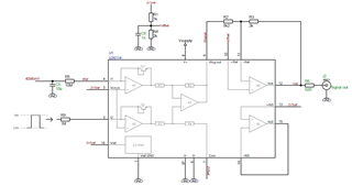
The measured response is shown in this screenshot (this is the falling edge of the signal at the input):
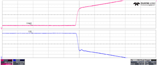
I'm aware that logarithmic amplifier have a bandwidth that decreases with input current, but I'd expect it to do so gradually. Here we observe a sharp knee.

Does this knee belong to the response of LOG114 or am I seeing something else? Is there a way to avoid it?

Thank you, Enpa

  • Hi Enpa,

    stay away from zero input currents. A log amplifier cannot operate in this region:

    enpa_log114_1.TSC

    See also this thread:

    https://e2e.ti.com/support/amplifiers-group/amplifiers/f/amplifiers-forum/1200094/log101-output-signals-have-ripples

    Kai

  • Hi Kai

    Thank you for looking into this.

    I tried to repeat the measurement with the signal generator set to output a low level of 2.6 V and things do indeed improve.

    In the real application we have a photodiode at the input of the LOG114. It is currently connected with its anode at 2.5V, so no reverse bias is applied.

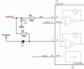
    We will try to apply some bias to increase the dark current and stay away from zero. If the dark current isn't sufficient, do you think that adding R9 could work?

    Enpa

  • Hello Enpa,

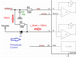
    In the circuit you posted above, a current source of (4.096V-2.5V)/15MΩ=~106.4nA is injected into the I2 input of the LOG114, where VCM_IN=+2.5V.

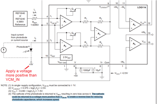
    The photodiode bias voltage is controlled by the difference between Vsupply and VCM_IN.  If you wanted to reverse bias the photodiode, one common way to accomplish this is to set the cathode to a voltage more positive than VCM_IN, to create a reverse bias for reducing the photodiode capacitance. See an example below.

    Thank you and Best Regards,

    Luis

  • Hi Enpa,

    yes, such an additional bias can be helpful. But with the 15M resistor the additional bias current would be 100nA which seems a bit high. I think 1nA would also do the trick and allow you a much wider signal range:

    enpa_log114_2.TSC

    Also keep in mind, that the 1nA bias current will impact the log conformity at small detector currents:

    1nA could be achieved with a R9 = 1.5G resistor.

    By the way, what is your detector capacitance and what is your signal frequency range?

    Kai

  • HI Enpa,

    In many applications, for example, when using InGaAs photodiodes, the photodiode sensor exhibit dark currents in the ~nanoampere range after applying a small reverse voltage.  This bias current is sufficient for many applications.  Nevertheless, the dark current can vary depending on your sensor. If available please provide the datasheet of your photodetector, and/or the capacitance, dark current vs reverse voltage to provide a suggestion above.   The LOG114 is specified to work with current as low as 100pA flowing into the I2 input.

    As you have mentioned, if the dark current of the photosensor isn't sufficient in your case, using R9 with a high value resistor to inject a small bias current , in the few 100s of picoamperes to nanoamp range could work as well. 

    Thank you and Regards,

    Luis  

  • Thank you Kai and thank you Luis for your answers

    The suggested additional current is indeed excessive. I will probably use a lower reference voltage to keep the resistor value within reasonable limits.

    A can't say yet what kind of photodiode we will use. Currently it's a PIN photodiode with a capacity of 40 pF, we are trying to redesign the optics to be able to work with a smaller detector.

    It should be possible to correct for the error introduced by the additional current in software.

    I'll build a couple of prototypes and I hope we will be able to find a solution.

    Thank you for your assistance.

    Enpa

  • Hi Enpa, 

    Thank you for the update. 

    Kind Regards,

    Luis