This thread has been locked.

If you have a related question, please click the "Ask a related question" button in the top right corner. The newly created question will be automatically linked to this question.

OPA828: Requirements for proper OPA627 replacement

Part Number: OPA828
Other Parts Discussed in Thread: OPA627, OPA140, OPA2828, OPA827

Hello,

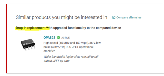
We have legacy TIA for photodiode that was using OPA627. TI lists OPA828 as being a "drop-in" replacement for it however after just swapping OPA627 to OPA828 device does not function as intended in fact we don't see any output signal from the device. Another variation of same device uses AD8610A as actual drop-in replacement and it does work well.

This is a repair project of a costly legacy hardware and unfortunately I don't have a schematics for it.

However traced it partially and here is how OPA627 is being used. Diode is biased with 5V and OPA627 is powered with +/- 5V.

Please advise how OPA627 can be replaced with OPA828. Thank you.

  • Volodymyr, 

    Can you describe what the behavior of the OPA828 is?  How does it misbehave?  Where did you see the recommendation of replacing the OPA627 with OPA828?  When I do a quick comparison of the two devices it seems that the bandwidth and slew rate of opa828 is quite a bit higher than the OPA627.  Normally extra bandwidth isn't an issue, but higher bandwidth devices may be more challenging to stabilize.  I think the OPA140 may be a closer match.  This device has a slightly lower bandwidth and slew rate, so if you need the full bandwidth and slew rate of the OPA627 it may not work.  All three devices are JFET input.  Note: if I use the cross-reference tool https://www.ti.com/cross-reference-search/en-us, on AD8610A it offers OPA140 as a cross.  Here is a comparison of key specification of all three devices:  opa828 vs opa627 vs opa140.xlsx

    I hope this information is helpful to you.

    Best regards, Art Kay

  • Hello Art,

    Thank you for checking on this.

    Right the idea was to replace OPA627 with newer better OpAmp to get even better BW etc. So far I only replaced OPA627 and traced the board to figure out how it's routed and didn't debug much as it's a bit difficult to do in-situ when instrument is running.

    This preamp is used to do electron detection at levels of 1pA - 10nA+ and it has adjustable gain from Low to Very High to adjust sensitivity accordingly. Typically at low current levels 1-100pA one would set preamp to Very High gain. So with installed OPA828 there is no signal at all except when preamp is set to Low gain and relatively high current 500pA then very noisy levels of electrons can be detected. I hope this provides some more background.

    Thank you for providing the cross link I will check it out.

    From OPA828 datasheet:

    "The OPA828 and OPA2828 (OPAx828) JFET input operational amplifiers are the next generation OPA627 and OPA827, combining high speed with high dc precision and ac performance. "

    and the bottom of OPA828 page www.ti.com/.../OPA828

    Thanks,

    Volodymyr

  • Hi,

    usually, the phase lead compensation in a TIA being used to keep the phase margin suffiently high, needs to be adjusted when replacing the OPAmp. So, I would carry out a phase stability analysis to find out whether the OPAmp and the feedback components are properly working together without causing instability. Make a search for "phase stability analysis" in this forum and see these TI's training videos on stability:

    https://www.ti.com/video/series/ti-precision-labs-op-amps.html

    Kai

  • Volodymyr,

    I agree with Kai.  If you look at the circuit with the new device using an oscilloscope do you see oscillations?  Attached is an article on transimpedance amplifiers.  The focus of the articles is noise analysis but stability is also covered (see page 14).  article18-noise11-Photodiode-Noise 1.pdf

    Kai,  Thanks as usual for your excellent help.

    Best regards,

    Art  

  • Thank you for all excellent suggestions.

    You were absolutely right about decoupling. After looking more carefully like you suggested regarding decoupling turns out designers put 1k resistors on V+ and V- rails to limit current draw by the OpAmps. Decoupling capacitors even stand out slightly on thermal camera and voltage at OPA828 pins are 1.5V/-1.8V instead of +/- 2.5V.

    Kai thank you for great resource I will make sure to check for phase stability after I fix power this issue.

  • Hi Volodymyr,

    inform us when you need support with the phase stability analysis.

    Kai